Card edge connector

a card edge connector and connector technology, applied in the direction of coupling device connection, coupling parts engagement/disengagement, electrical equipment, etc., can solve the problem of more difficult to insert the module into the card edge connector

Inactive Publication Date: 2011-04-12
HON HAI PRECISION IND CO LTD
View PDF11 Cites 37 Cited by
  • Summary
  • Abstract
  • Description
  • Claims
  • Application Information

AI Technical Summary

Problems solved by technology

The increase in the number of contacts would raise the resistance force considerably

Method used


Image

  • Card edge connector
  • Card edge connector
  • Card edge connector

Examples


Embodiment Construction

[0016]Reference will be made to the drawing figures to describe the present invention in detail, wherein depicted elements are not necessarily shown to scale and wherein like or similar elements are designated by same or similar reference numeral through the several views and same or similar terminology.

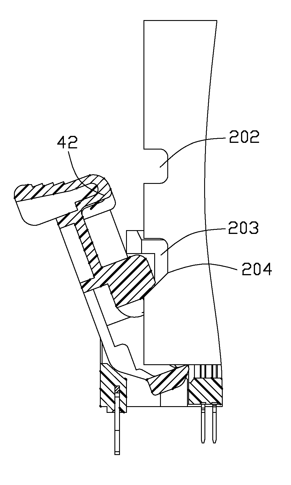
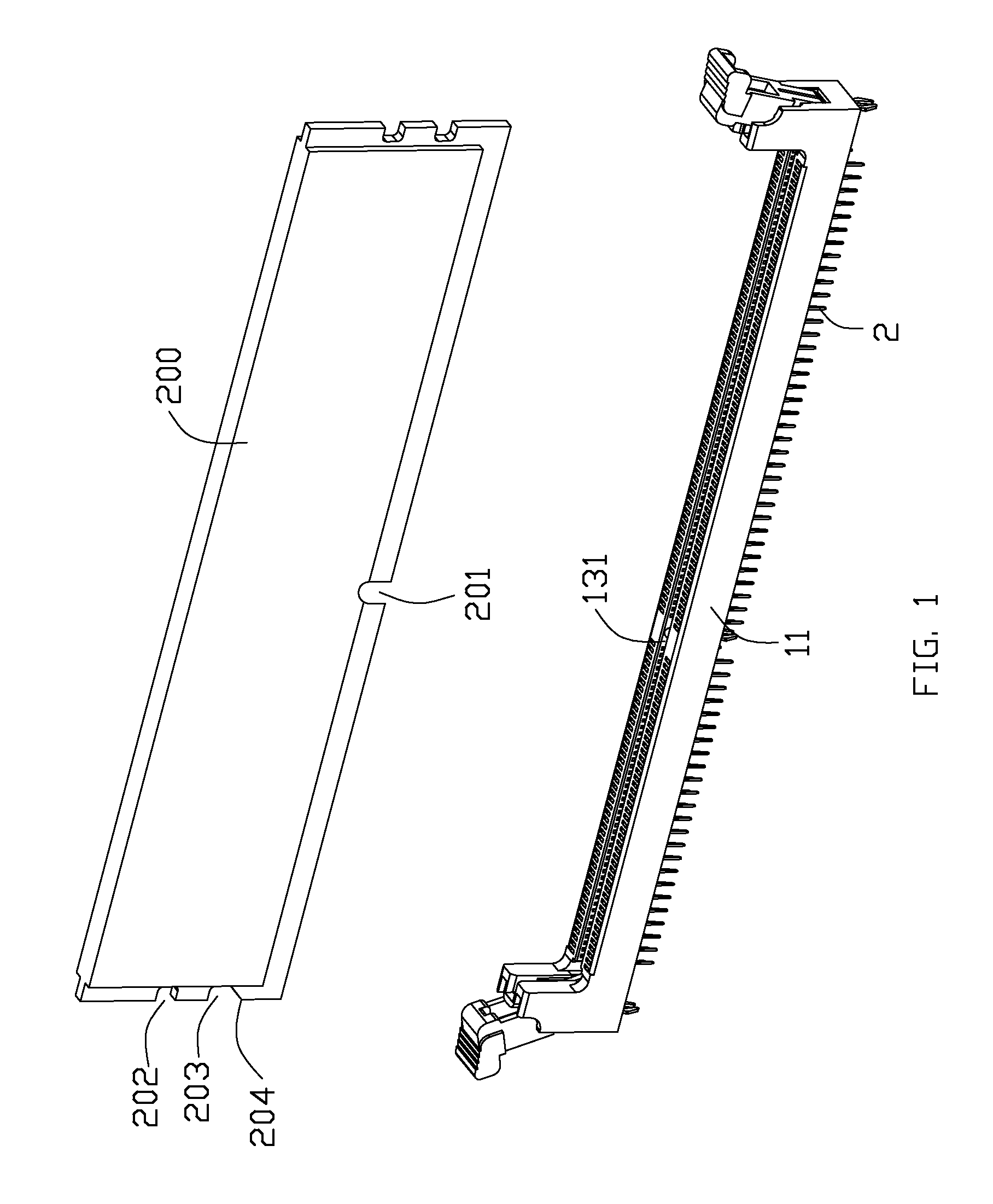
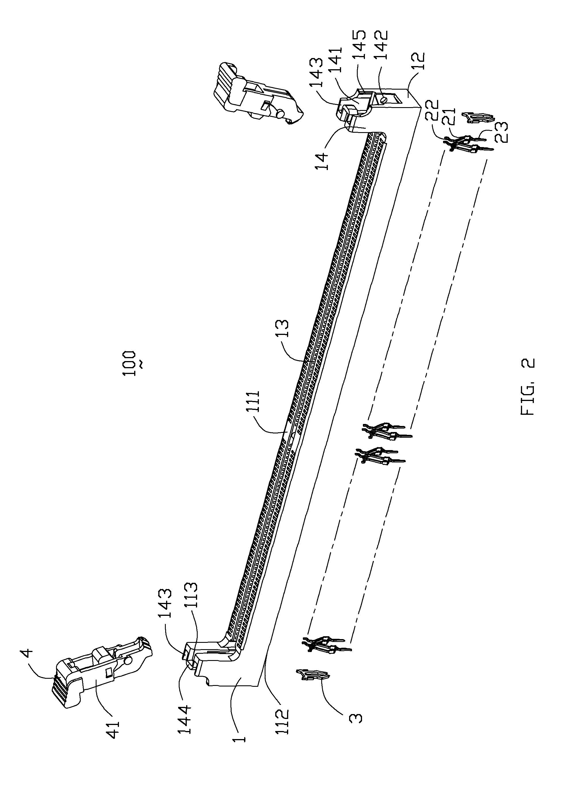
[0017]Referring to FIGS. 1-2, a card edge connector 100 according to the present invention is preferably a memory socket to be mounted on a mother printed circuit board, comprises an elongated housing 1 having a pair of longitudinal side walls 11 extending along a lengthwise direction thereof, a pair of end walls 12 extending from opposite ends of the side walls 11 to connect the side walls 11, an elongated central slot 13 formed therebetween for receiving a corresponding memory module 200 therein. The side walls 11 have a mating face 111 from which the central slot 13 is recessed and a mounting face 112 for mounting on the mother printed circuit board.

[0018]A plurality of contacts 2...


PUM


Abstract

A card edge connector for receiving a module and includes an insulative housing having a mounting face, a pair of side walls with a central slot formed therebetween, a tower portion extending upwardly from the side wall; a number of contacts mounted to the housing and each defining a retaining portion to fix with the housing, a deflectable contacting arm extending upwardly from the retaining portion and a soldering portion extending downwardly from the retaining portion and projecting beyond the mounting face; and an ejector rotatably mounted on the tower portion of the housing. The ejector includes a base portion, an ejecting portion extending inwardly from the base portion and protruding into the central slot to eject the memory module from the central slot and a cam lobe extending inwardly from the base portion to drive the module down, the cam lobe is located above the ejecting portion.

Description

BACKGROUND OF THE INVENTION[0001]1. Field of the Invention[0002]The present invention generally relates to a card edge connector for receiving a module and more particularly to a card edge connector including means to reduce insertion force of the module.[0003]2. Description of Related Art[0004]A card edge connector (memory socket) is used to hold a memory module such as a DDR 3 module and to electrically couple such module to a mother printed circuit board on which the card edge connector is mounted. The card edge connector generally includes an elongated insulative housing having a central slot for receiving the module, a plurality of metal contacts extending into the slot for electrically connecting with the module, a pair of ejectors rotatablely attached to two opposite ends of the housing. The ejector is adapted to latch with a locking notch on a side edge of the module in a working state and to bias against a bottom edge of the module to eject the module out of the slot in an ...

Claims


Application Information

Patent Timeline
IPC IPC(8): H01R13/62
CPCH01R12/7005H01R12/737H01R12/721
Inventor HARLAN, TOD M.MALEHORN, RICHARD LEE
Owner HON HAI PRECISION IND CO LTD
Why Eureka
Try Eureka