Transseptal Puncture Needle and Needle Assemblies

a transseptal and needle technology, applied in the direction of dilators, manufacturing tools, catheters, etc., can solve the problems of difficult access to the left atrium through the pulmonary artery, difficult access from the left ventricle, and difficult access to the left atrium with a catheter, so as to reduce the insertion force and reduce the risk of tissue coring , the effect of minimizing the risk of inadvertent insertion

Active Publication Date: 2009-07-02
ST JUDE MEDICAL ATRIAL FIBRILLATION DIV
View PDF34 Cites 43 Cited by
  • Summary
  • Abstract
  • Description
  • Claims
  • Application Information

AI Technical Summary

Benefits of technology

[0030]An advantage of the present invention is that it reduces the insertion force necessary, thereby minimizing the risk of inadvertently puncturing the left atrial wall just after crossing the septum.
[0031]Another advantage of the present invention is that it provides a reduced risk of tissue coring.
[0032]Still another advantage of the present invention is that it reduces skiving of dilator and / or sheath particles as the needle is introduced.
[0033]A further advantage of the present invention is that it provides desirable tactile feedback to the surgeon or surgical system in use.
[0034]The foregoing and other aspects, features, details, utilities, and advantages of the present invention will be apparent from reading the following description and claims, and from reviewing the accompanying drawings.

Problems solved by technology

The most difficult chamber of the heart to access with a catheter is the left atrium.
Access to the left atrium through the pulmonary artery is not possible.
Approaches from the left ventricle are difficult, may cause arrhythmias, and may present difficulty in obtaining stable catheter positioning.
On the other hand, if the needle is too sharp, it may not provide sufficient feedback to the surgeon to let the surgeon know when the needle pierces the inter-atrial septum.
In addition, advancement of a sharp needle tip or a needle tip with a sharp edge through the dilator or sheath may cause particles to be skived from the interior surface of the dilator or sheath.

Method used


Image

  • Transseptal Puncture Needle and Needle Assemblies
  • Transseptal Puncture Needle and Needle Assemblies
  • Transseptal Puncture Needle and Needle Assemblies

Examples


Embodiment Construction

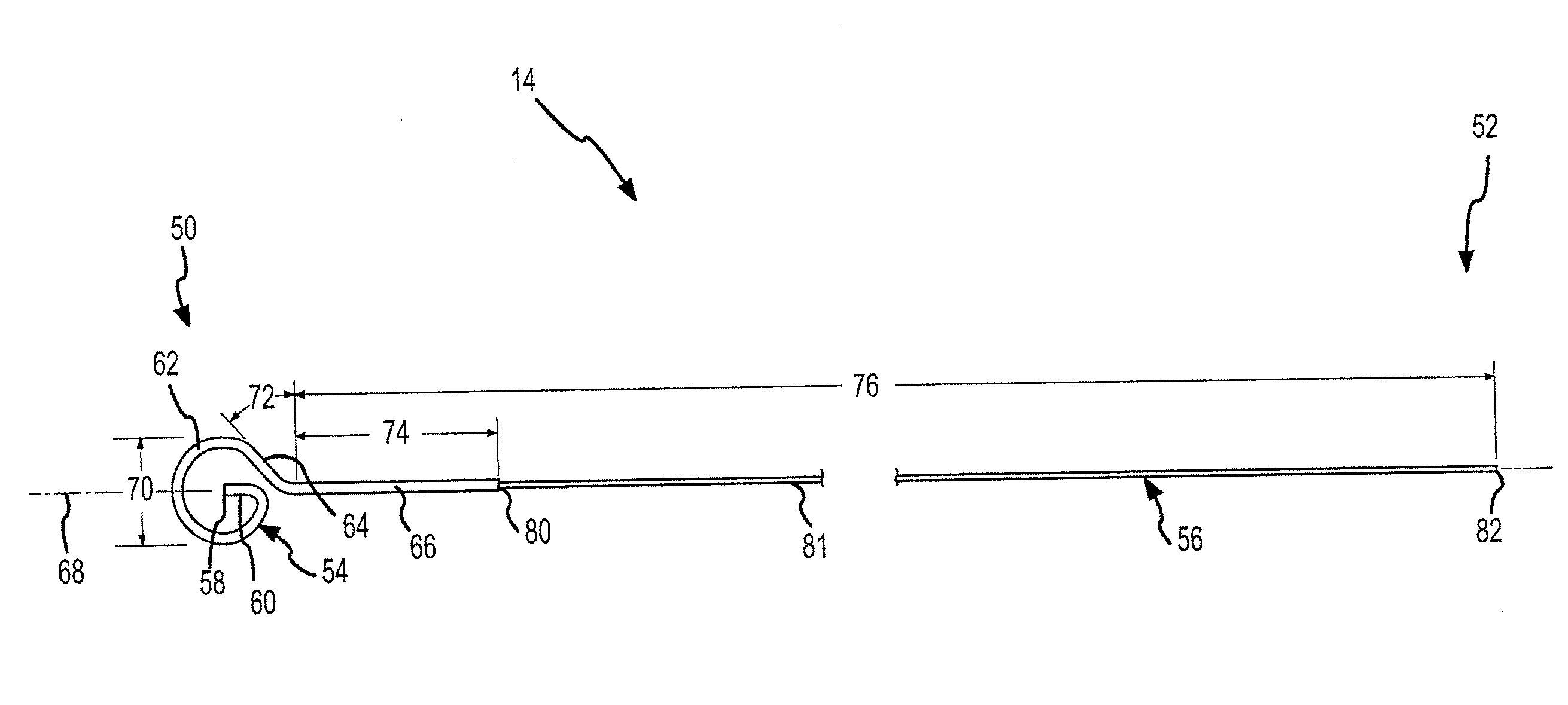
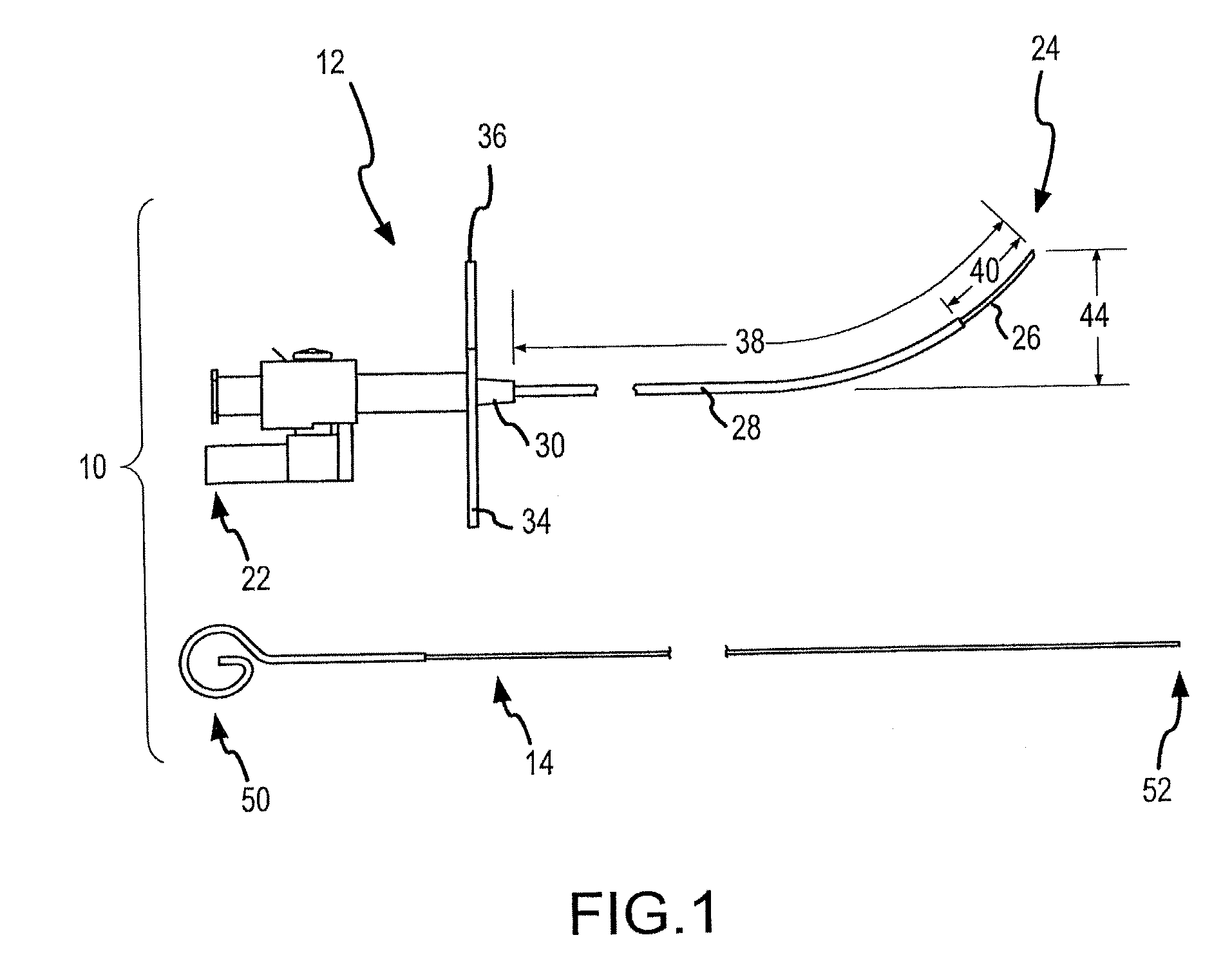
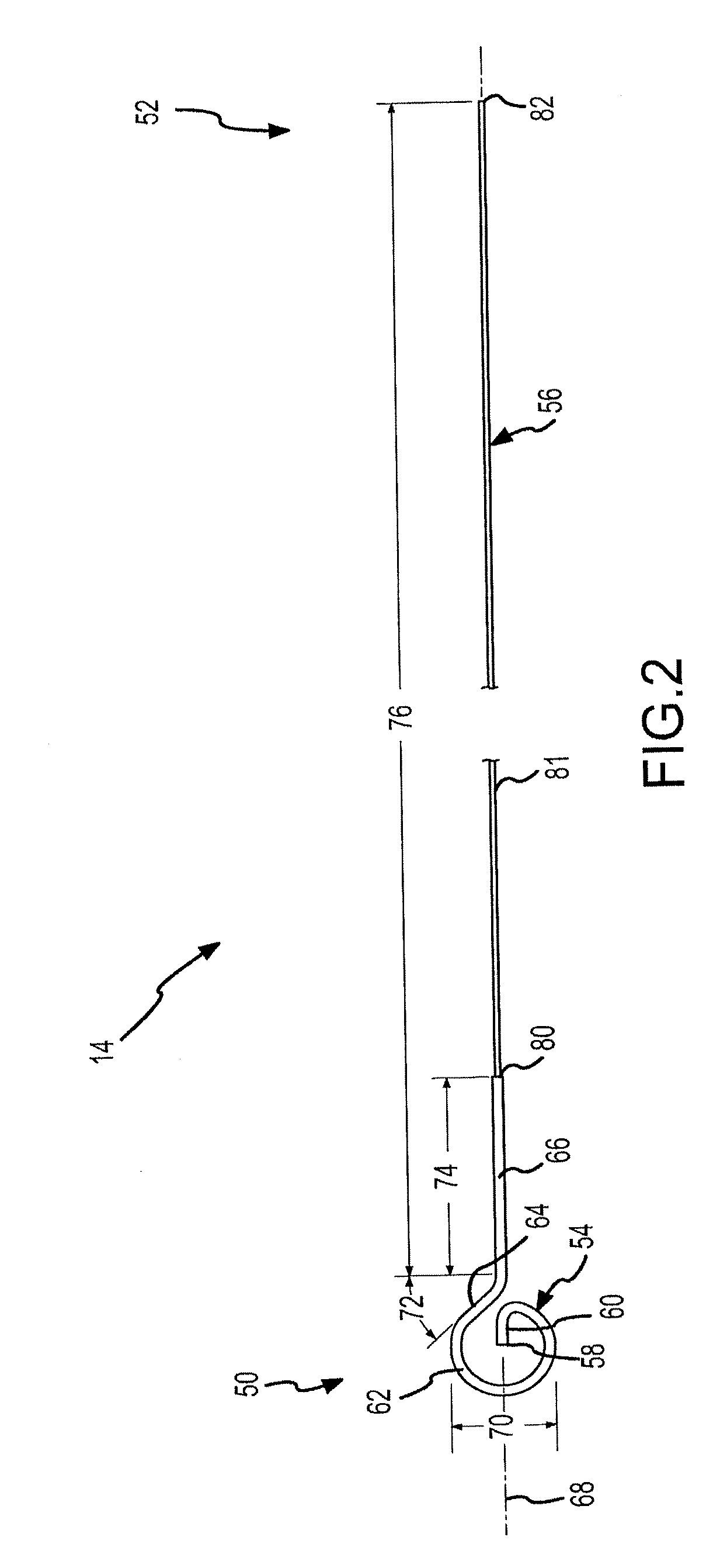
[0056]The present invention comprises curved transseptal puncture needles 12 and needle assemblies 10 (i.e., the combination of a curved transseptal puncture needle 12 and its stylet 14 as shown in FIG. 1) that facilitate insertion through curved transseptal introducers 16 (i.e., sheaths, or sheath 18 and dilator 20 combinations as shown in, for example, FIG. 11). The needle assemblies 10 and introducers 16 permit, for example, left atrial access from the venous system for catheter diagnosis and treatment (e.g., ablation of arrhythmogenic cardiac tissue). Each curved transseptal puncture needle 12 has a specific tip configuration and axial orientation, the combination of which is designed to facilitate low force, smooth insertion through the introducer 16 while reducing the risk of introducing dilator particulate removed by the needle tip (e.g., skiving) into a patient's left heart or blood stream, and while reducing the amount of coring that may occur during puncture of the patient...


PUM

PropertyMeasurementUnit
wedge angleaaaaaaaaaa
interbevel angleaaaaaaaaaa

Abstract

A transseptal needle includes an elongate needle body having a distal end and a proximal end and a cannular needle tip located proximate the distal end of the needle body. The needle tip has a distal segment, a proximal segment, and a longitudinal axis. An inner surface of the needle tip defines a passageway spanning at least a portion of the needle tip, and an outer surface of the needle tip defines a wall with the inner surface. The distal segment of the needle tip also includes a wedge surface and a dome-shaped region. The wedge surface forms a wedge angle of other than 90 degrees relative to the longitudinal axis. The dome-shaped region, which intersects the wedge surface, includes at least two bevels that intersect the wedge surface and that intersect each other at one or more points on the needle tip.

Description

CROSS-REFERENCE TO RELATED APPLICATIONS[0001]This application claims the benefit of United States provisional application no. 60 / 916,565, filed May 8, 2007. This application is a continuation-in-part of U.S. application Ser. No. 11 / 646,525, filed Dec. 28, 2006, which claims the benefit of U.S. provisional application no. 60 / 800,854, filed May 17, 2006. This application is also a continuation-in-part of U.S. application Ser. No. 10 / 947,817, filed Sep. 22, 2004. This application is also related to U.S. application Ser. No. 11 / 647,312, filed Dec. 29, 2006. All of the foregoing are hereby incorporated by reference as though fully set forth herein.BACKGROUND OF THE INVENTION[0002]a. Field of the Invention[0003]The instant invention relates to assemblies and methods for puncturing, or piercing, tissue within the body, including, for example, transseptal access systems and methods for accessing the left atrium from the right atrium by crossing the fossa ovalis. In particular, the instant i...

Claims


Application Information

Patent Timeline
Patent Type & Authority Applications(United States)
IPC IPC(8): A61B17/34A61M5/00A61M29/00B23P11/00
CPCA61B17/00234A61B17/3478A61B2017/00247A61B2017/0046A61B2018/00392A61M2025/0089A61M2025/0681A61B2090/034Y10T29/49826
Inventor BEDNAREK, MICHAEL C.GURUSAMY, RAVISANKARSCHNELLMANN, HANSSTANGENES, TODD
Owner ST JUDE MEDICAL ATRIAL FIBRILLATION DIV
Why Eureka
Try Eureka