Disk apparatus

a technology of disk drive and cartridge, which is applied in the direction of data recording, instruments, undesired vibration/sound insulation/absorption, etc., can solve the problems of affecting the size reduction of the drive, affecting the efficiency of the drive, and affecting the performance of the drive, so as to reduce the load on the damper

Inactive Publication Date: 2005-09-15
PANASONIC CORP
View PDF12 Cites 37 Cited by
  • Summary
  • Abstract
  • Description
  • Claims
  • Application Information

AI Technical Summary

Benefits of technology

[0162] The present invention aims at providing a small disk drive which reduces a l...

Problems solved by technology

However, the conventional optical disk record/reproduce drive has a problem that the drive is complex and large and there is a large load upon the damper which blocks external vibrations.
Further, the drive load is large since it is necessary to release the shutter of the cartridge, vertically drive the traverse base and position the cartridge all at the same time to thereby realize the structure which holds the cartridge and the optical disk as one integrated unit, and a special drive structure is necessary for the loading mechanism as the cartridge and the optical disk need be held as one integrated unit, which not only hinder an endeavor for size reduction of the drive but also leads to a following further problem which prohibits size reduction.
(2) Although the cartridge pressing springs urges the cartridge against the tray through the cartridge pressing members (rollers) during loading, if a foreign matter gets nipped between the cartridge pressing members and the cartridge, the surface of the cartridge may get damaged.
(4) When there is a large misregistration of the cartridge, the forward/backward direction urging force exerted by the cartridge pre-loading member and the friction force upon the tray exerted by the cartridge pressing springs may make it difficult to insert the alignment pins and may prohibit accurate positioning of the cartridge.
There is a problem that a child with small hands or an aged person whose force for grasping at the cartridge with fingertips, in particular, can not easily place the cartridge or take out the cartridge.
There is also a possibility that diffracted light of the strong laser light reflected by the recording surface of the disk will leak out at the front opening, and depending on installation of the drive, will impinge upon an eye and damage a retina.
In the event that the position in the height direction at which the optical disk record/reproduce drive is installed is about the same as or higher than the height of eyes of an operator who performs the insertion, the insertion over the cartridge becomes unnatural and the drive is therefore inconvenient to use.
(3) Therefore, when the cartridge is placed on the tray in a wrong state and the tray is loaded with the cartridge struck against the front wall surface, the left wall surface or the right wall surface because of a misoperation made by an operator, the tray opening in the optical disk record/reproduce drive and the cartridge interfere with each other in the middle of the loading of the tray and the loading is consequently interrupted.
Meanwhile, the structure in which the cartridge itself avoids a misoperation during loading may lead to a scratch on the surface of the cartridge, or in the worse case, destruction of the cartridge.
However, since the detecting switch as well moves together with the tray, a complex arrangement of wiring members for signal transmission is needed, which in turn results in lack of reliability.
Therefore, a large drive torque is necessary, which creates a loading noise when the gear ratio is selected right at an appropriate speed for cartridge loading since the speed of loading means which loads in a tray or the like becomes too fast in the absence of a media or against use of a naked disk.
(1) The external shape of the traverse base is large since the alignment pins and the state detecting switches are integrated with the traverse base which holds the spindle motor and the like, and as it is necessary to vertically drive the heavy traverse base for loading or ejection, the vertical drive force for the traverse base increases, and a noise du...

Method used


Image

  • Disk apparatus
  • Disk apparatus
  • Disk apparatus

Examples


first preferred embodiment

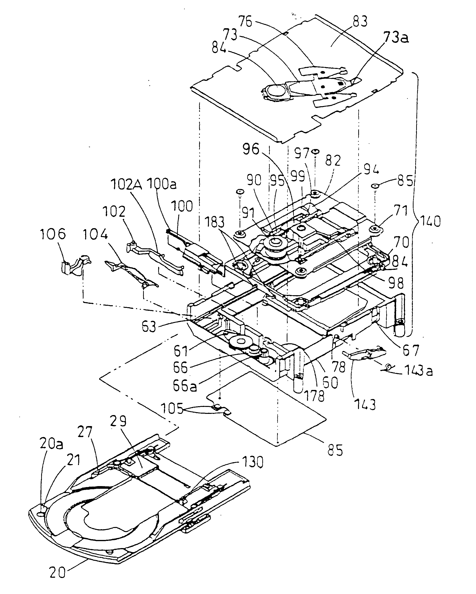
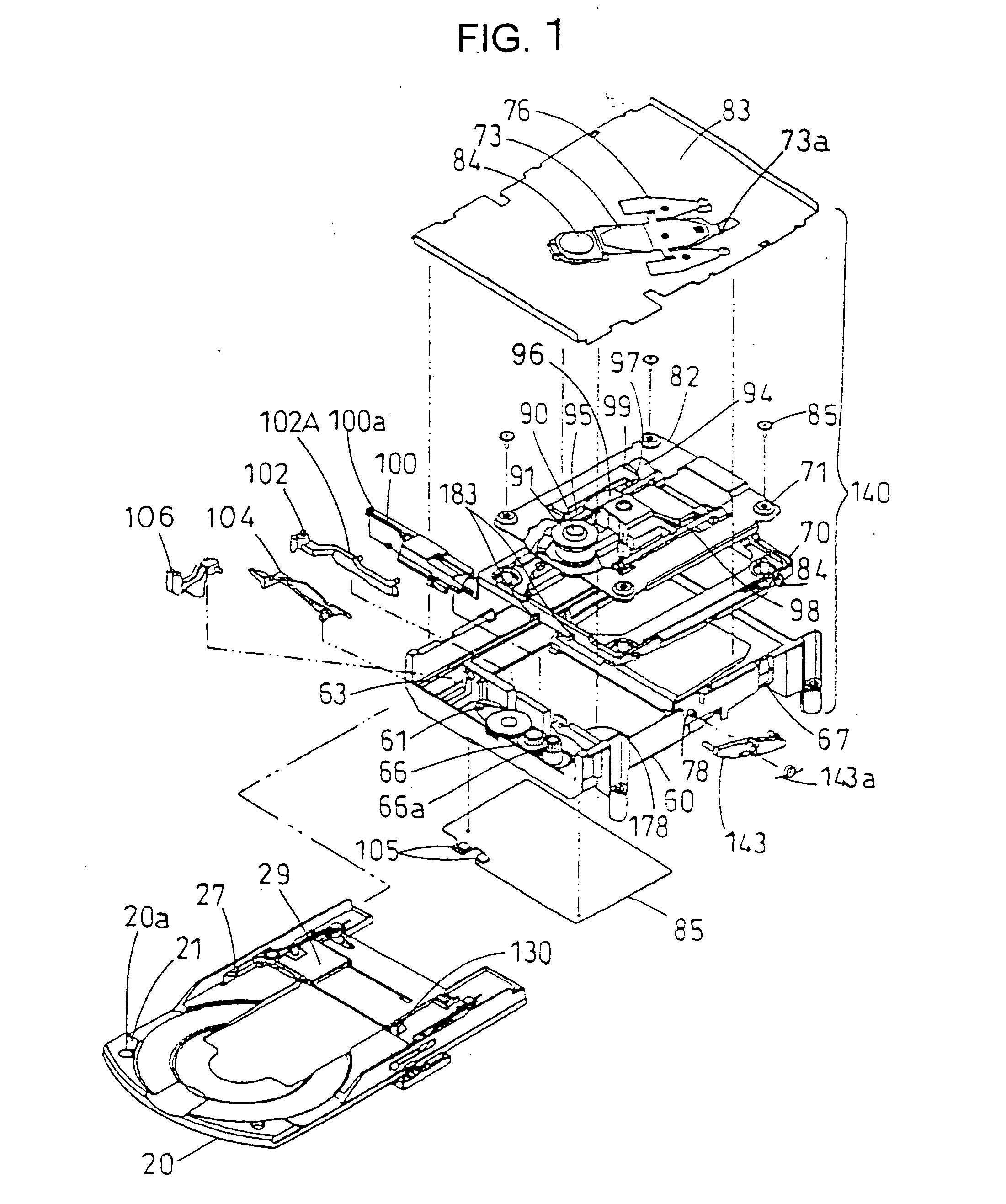
[0375] A cartridge holding mechanism of an optical disk record / reproduce drive according to a first preferred embodiment of the present invention will be described with reference to FIGS. 1 through 7. FIG. 1 shows the first preferred embodiment of the optical disk record / reproduce drive according to the present invention. In FIG. 1, denoted at 140 is a main unit of the optical disk record / reproduce drive, denoted at 20 is a tray which mounts a cartridge and a naked optical disk, denoted at 1 is a cartridge, and denoted at 10 is a disk which is stored in a cartridge.

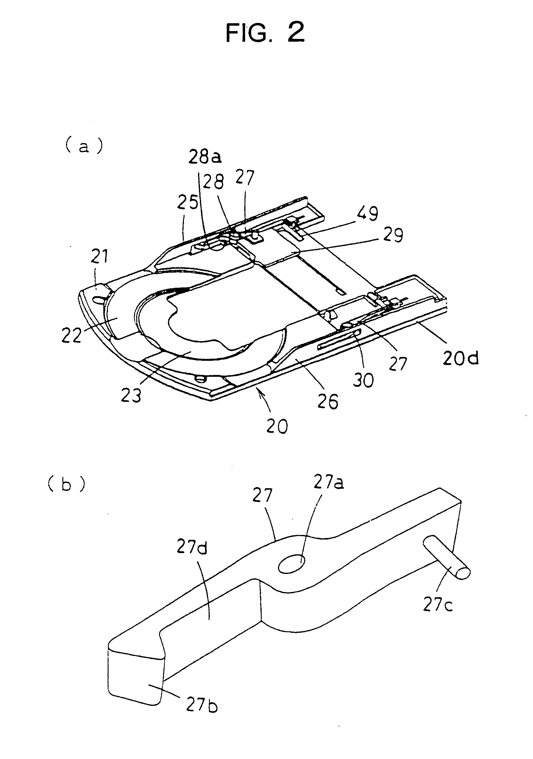
[0376] (Structure of Tray)

[0377] There are two concave portions, one large and the other small, formed in a concentric arrangement at the center of a cartridge seating surface 21 of the tray 20. The concave portion having a large diameter is a large diameter disk seater 22 while the concave portion having a small diameter is a small diameter disk seater 23, and either one is used in accordance with the outer diameter of...

second preferred embodiment

[0442] A second preferred embodiment of the present invention will be described with reference to FIG. 8. This embodiment is directed to attachment of the rubber dampers in the first preferred embodiment. There are holes 300 which are approximately circle are formed on the four corners of the traverse base 82, and the rubber dampers 71, which are cylindrical yet concaved in the middle to be shaped like a lug, are fit in the same at the concaved portions 71a.

[0443] There are through holes 71b along the vertical direction of the rubber dampers 71, bosses 70a which have a cylindrical shape for instance disposed upright to the traverse holder 70 are inserted through the through holes 71b, and fixing screws 85 are put in the screw holes 70b which are formed at the top ends of the bosses, thereby preventing dropping of the rubber dampers 71.

[0444] In the rubber dampers 71, predetermined misregistrations H are created between the inter-hole distances between the holes 300 of the traverse...

third preferred embodiment

[0448] A third preferred embodiment of the present invention will be described with reference to FIG. 9. This embodiment is directed to setup of the resonance frequency of the rubber dampers in the first preferred embodiment. The rubber dampers are of a material which exhibits both a spring characteristic and a vibration absorption characteristic and therefore inevitably has a primary resonance frequency. The primary resonance frequency becomes lower as a soft rubber material whose vibration absorption characteristic is higher is used, which realizes setup to a frequency close the rotational frequency of the optical disk.

[0449] However, since an optical disk requires a step of molding a resin into a thin disk and a step of bonding, the thickness of the disk always becomes uneven and a centering. error always occurs during the bonding, which makes the center of rotation of the optical disk and the center of gravity fail to match with each other. This deviation is called a mass eccen...


PUM


Abstract

A disk drive comprises a cartridge holding mechanism which has a small size and reduces a damper load. The disk drive comprises: a spindle motor 91 which mounts and rotates a disk; a traverse base 82 which holds the spindle motor 91; a rubber damper 71 which flexibly holds the traverse base 82; a mechanical chassis 60 which holds the traverse base 82 through the rubber damper 71; a tray 20 which mounts a cartridge 1 in which a disk is housed; and a loading motor 61 which moves the disk in the cartridge 1 close to the spindle motor 91 or away from the spindle motor 91. The cartridge 1 is supported by the mechanical chassis 60 through the tray 20.

Description

FIELD OF THE INVENTION [0001] The present invention relates to a disk drive and a disk loading method for an optical disk drive applied to a player, a recorder or the like which records in, reproduces from, or records in and reproduces from a disk such as an optical disk. [0002] More particularly, the present invention relates to holding of a cartridge by means of a tray which mounts a disk stored in a cartridge and a naked disk, loads a disk into inside a disk drive (loading) or ejects a disk out of the disk drive (ejection), and to a cartridge holding mechanism which holds a disk which is stored in a cartridge. [0003] The present invention also relates to a loading method, a loading mechanism and a loading drive for loading a tray into inside a disk drive (loading) or ejects a disk out of the disk drive (ejection). [0004] The present invention further relates to a lock mechanism of a door for blocking an opening which appears after loading of a tray which mounts a cartridge contai...

Claims


Application Information

Patent Timeline
IPC IPC(8): G11B17/028G11B17/04G11B33/08
CPCG11B17/0286G11B17/0288G11B33/08G11B17/056G11B17/057G11B17/047G11B17/04
Inventor UENO, SHIGETONAKA, TERUYUKIMAEDA, SHINICHIISHIZUKA, MASAKAZUKABUTA, YASUOOBATA, ISAOTOKUNAGA, TOMOSHIYOSHIDA, AKIRA
Owner PANASONIC CORP
Why Eureka
Try Eureka