Apparatus for projection and methods for using the same

a technology for projection apparatus and projection body, applied in the direction of projectors, instruments, optics, etc., can solve the problems of difficult movement of projectors, difficult transportation and setup, and relatively bulky projectors, etc., and achieve the effect of convenient adjustment, convenient transportation, and easy, quick and efficient operation

Inactive Publication Date: 2016-07-12
BEM WIRELESS
View PDF12 Cites 0 Cited by
  • Summary
  • Abstract
  • Description
  • Claims
  • Application Information

AI Technical Summary

Benefits of technology

[0012]The present invention relates to a projection apparatus capable of projecting high quality video in a convenient mobile casing. Specifically, the present invention relates to a projector, which is disposed within a casing in alignment with the casing having a handle in a first configuration. More, specifically, the projector may be rotatably positioned within the casing into a second configuration to focus a video image against a background. Specifically, the casing supports the projector in the second configuration, such that the projection apparatus may stand freely on its own. The casing includes a kickstand that is flush with the casing in the first configuration and is rotatably positioned away from the casing to create a stand for use in the second configuration.

Problems solved by technology

Generally, these projectors are relatively bulky and fragile, and typically are difficult to transport and set up where needed to project an image.
Regularly, projectors are difficult to move because of their expensive, bulky, and fragile nature.
Specifically, modern projectors utilize a high power light source that may easily break, that may project an image through a lens, which may also be fragile.
These may also be relatively fragile, and may, together, create a relatively heavy apparatus that may be somewhat large and difficult to move.
Moving expensive, bulky, and fragile devices compels a person to act slowly and meticulously in order to avoid dropping or damaging the devices.
Frequently moving the projectors in and out of cases or bags increases the risk of damaging the projectors.
Further, most cases and bags are soft-shelled cases and do not provide much rigid support for video projectors.
However, ceiling mounting a projector, while generally freeing the projector from harm, may cause it to be beyond reach for easy adjustments.
Further, once a projector is mounted, it is very difficult to move or remove it.
However, setting up a projector to project an image onto a screen, wall or other surface, may be very difficult to do.
Manually adjusting these pads or feet is time-consuming and difficult.

Method used


Image

  • Apparatus for projection and methods for using the same
  • Apparatus for projection and methods for using the same
  • Apparatus for projection and methods for using the same

Examples


Embodiment Construction

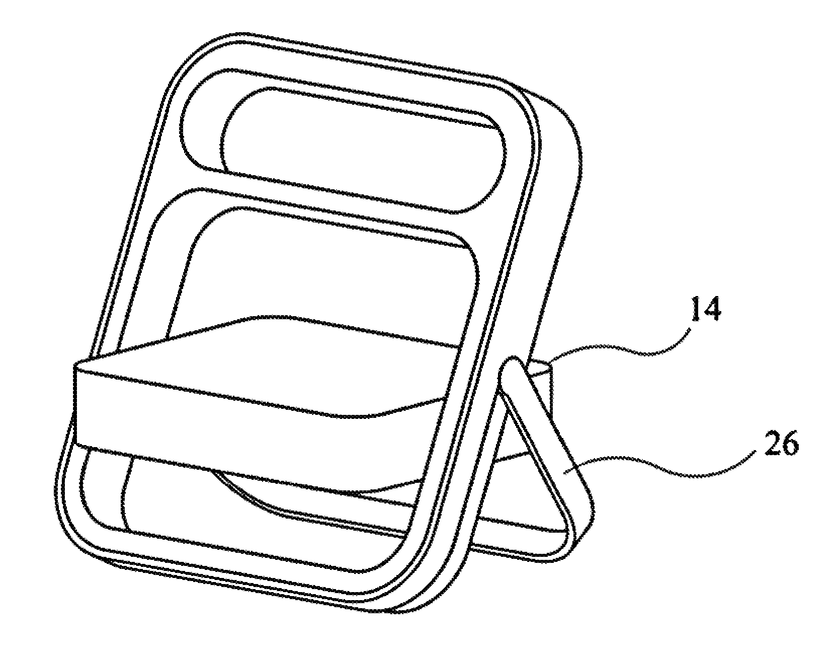
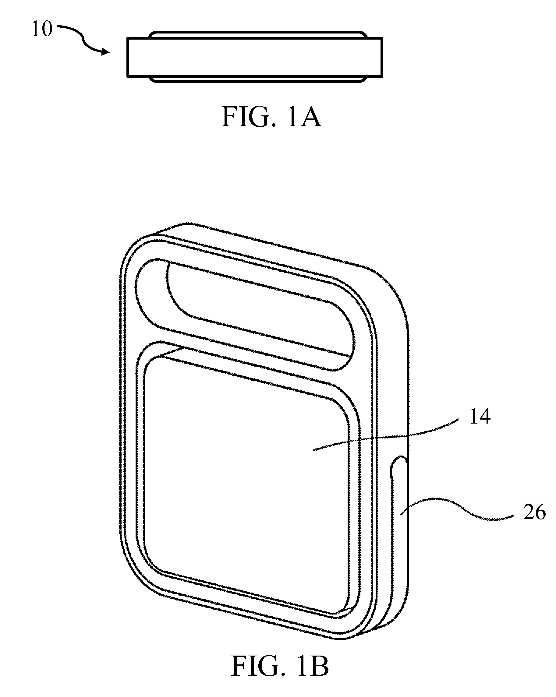
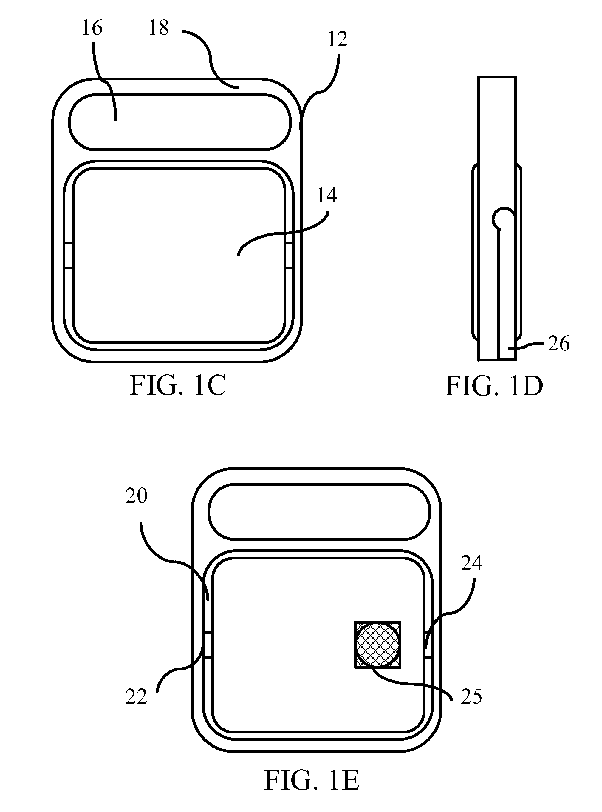
[0038]The present invention relates to a projection apparatus capable of projecting high quality video in a convenient mobile casing. Specifically, the present invention relates to a projector, which is disposed within a casing in alignment with the casing having a handle in a first configuration. More, specifically, the projector may be rotatably positioned within the casing into a second configuration to focus a video image against a background. Specifically, the casing supports the projector in the second configuration, such that the projection apparatus may stand freely on its own. The casing includes a kickstand that is flush with the casing in the first configuration and is rotatably positioned away from the casing to create a stand for use in the second configuration.

[0039]Now referring to the figures, wherein like numerals refer to like parts, FIGS. 1A-1E illustrate a projection apparatus 10 in a first configuration in a preferred embodiment of the present invention. The pro...


PUM


Abstract

The present invention relates to a projection apparatus capable of projecting high quality video in a convenient mobile casing. Specifically, the present invention relates to a projector, which is disposed within a casing in alignment with the casing having a handle in a first configuration. More, specifically, the projector may be rotatably positioned within the casing into a second configuration to focus a video image against a background.

Description

[0001]This application claims priority under 35 U.S.C. 119(e) to U.S. Provisional Patent Application No. 61 / 749,577, filed on Jan. 7, 2013, which is incorporated by reference herein in its entirety.TECHNICAL FIELD[0002]The present invention relates to a projection apparatus capable of projecting high quality video in a convenient mobile casing. Specifically, the present invention relates to a projector, which is disposed within a casing in alignment with the casing having a handle in a first configuration. More, specifically, the projector may be rotatably positioned within the casing into a second configuration to focus a video image against a background. Specifically, the casing supports the projector in the second configuration, such that the projection apparatus may stand freely on its own. The casing includes a kickstand that is flush with the casing in the first configuration and is rotatably positioned away from the casing to create a stand for use in the second configuration...

Claims


Application Information

Patent Timeline
Patent Type & Authority Patents(United States)
IPC IPC(8): G03B21/14G03B21/30
CPCG03B21/145G03B21/30G03B21/142
Inventor NAKAMURA, MICHAELKATZEL, BRYANMORROW, JAMES D.
Owner BEM WIRELESS
Why Eureka
Try Eureka