Moving picture decoding method and moving picture encoding method
a technology of moving picture and encoding method, which is applied in the direction of color television with bandwidth reduction, signal generator with optical-mechanical scanning, signal system, etc., can solve the problem of large amount of coded bits still needed for motion vectors, overhead of the amount of coded bits, and insufficient prediction accuracy of each motion vector
- Summary
- Abstract
- Description
- Claims
- Application Information
AI Technical Summary
Benefits of technology
Problems solved by technology
Method used
Image
Examples
embodiment 1
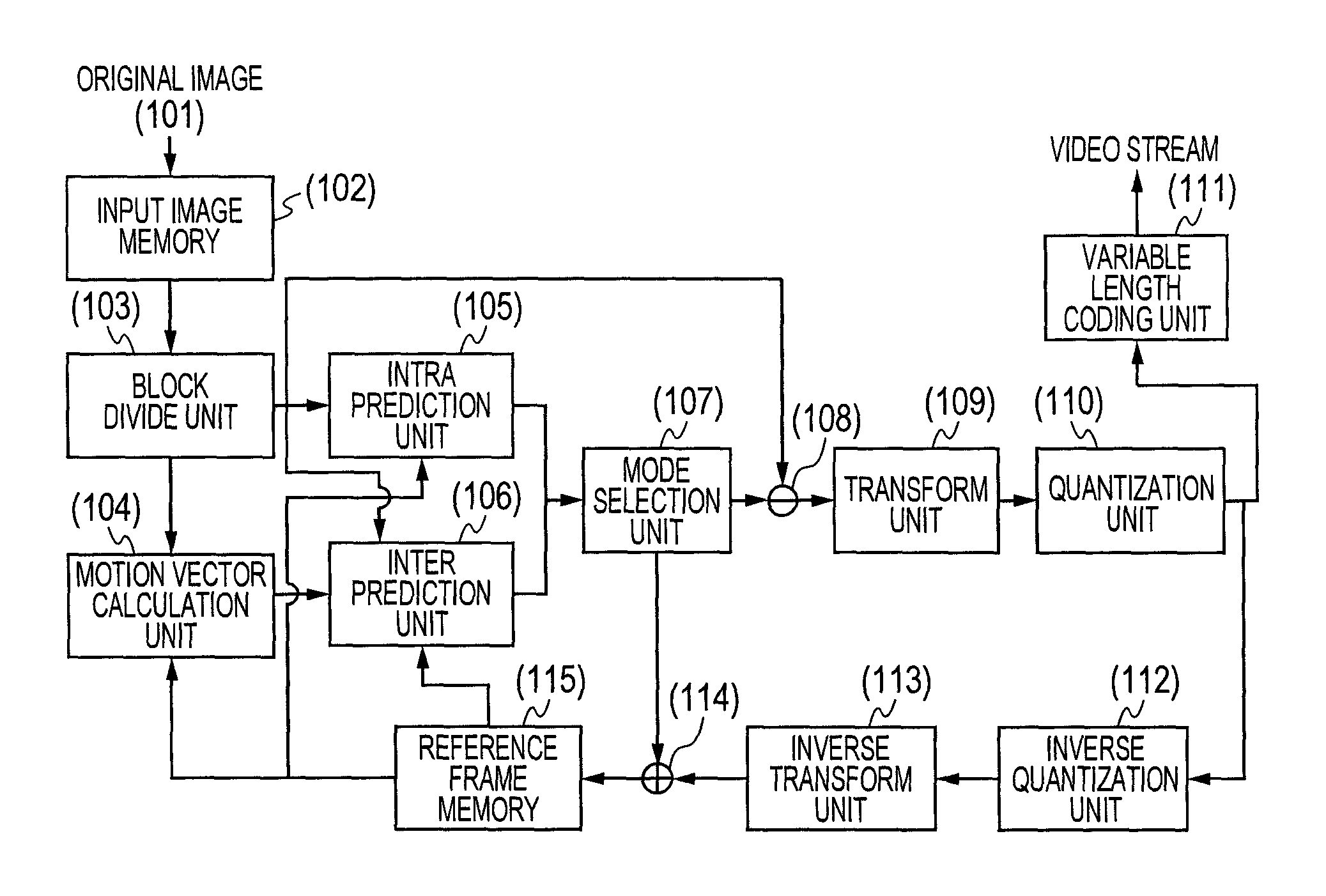
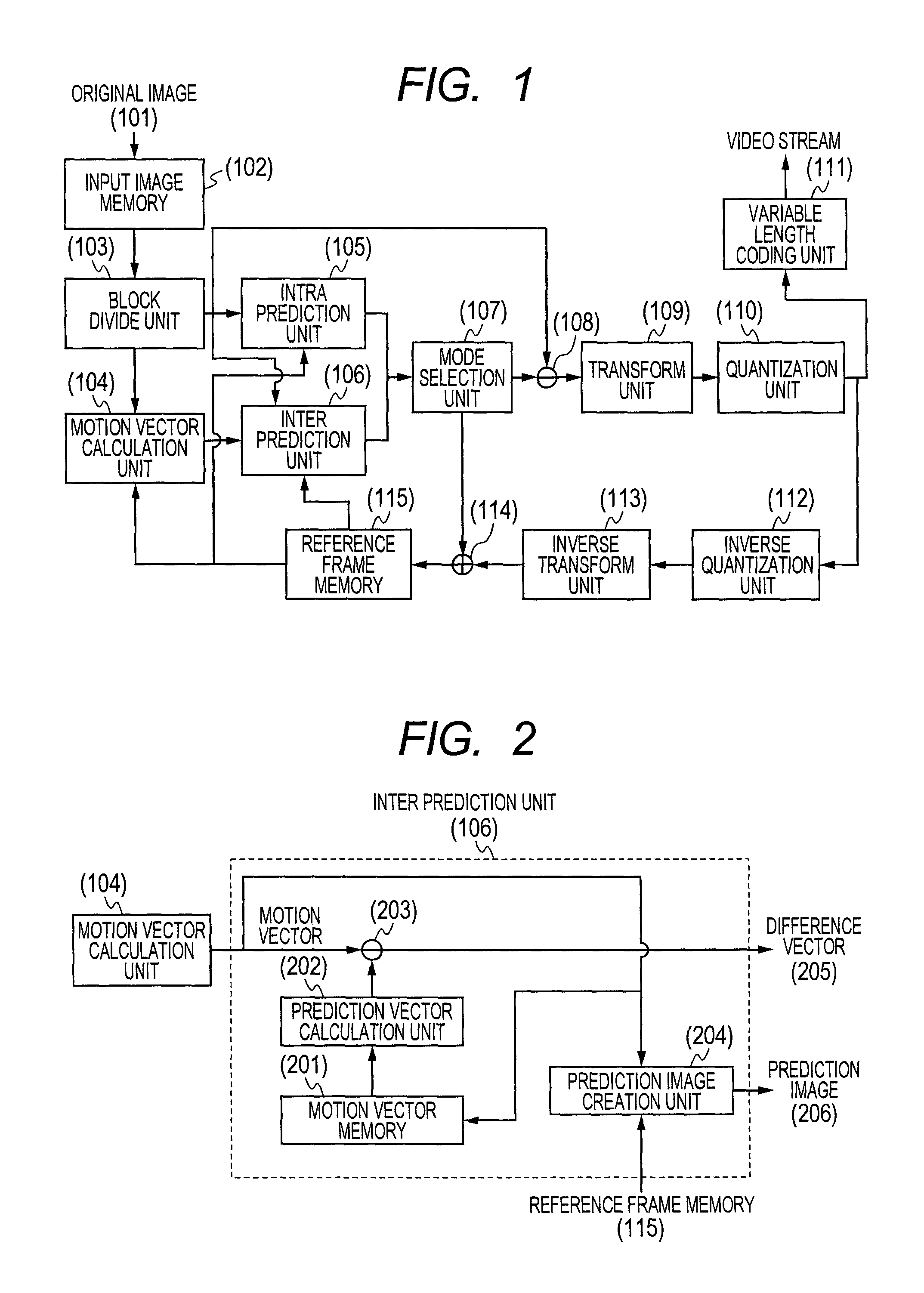
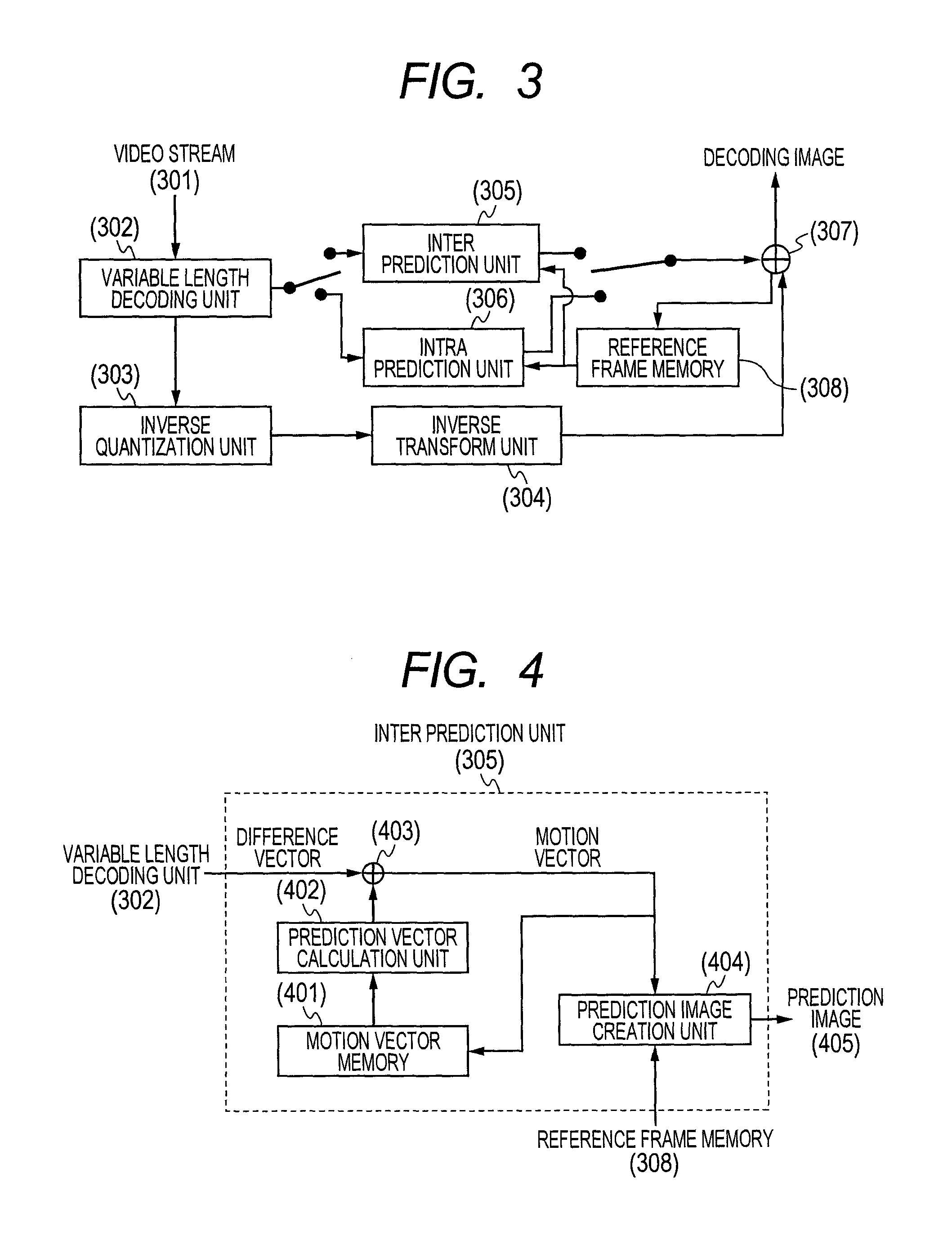
[0036]The embodiment 1 uses information about a combined area when a prediction vector of a target block is computed. That is, when the combined area exists around the target block, it is determined that the target block also includes a part of the same object as that included in the combined area. The prediction vector is calculated based on the motion vector of each block included in the combined area.
[0037]Thus, since the prediction vector can be calculated based on a motion vector of a motion area that exists in the vicinity of a target area, it is possible to improve prediction accuracy for the motion vector. Further, the method of calculating the prediction vector is improved to reduce the amount of coded bits for the motion vector and enable an improvement in compression efficiency.
[0038]FIG. 7 is a diagram conceptually showing one example of a prediction vector PMV computing method according to the present embodiment.
[0039]Consider, for example, where a block (703) including...
embodiment 2
[0069]In the embodiment 1, the prediction accuracy is improved where the target block is included in its corresponding peripheral object area. On the other hand, in the embodiment 2, a prediction vector PMV of a target block is calculated using encoded or decoded previous frames. It is thus possible to improve prediction accuracy where a target block is located in the boundary of object areas, for example.
[0070]FIG. 9 is a diagram showing one example using encoded previous frames.
[0071]Here, the combining of motion vectors MV is performed to a frame (display time t=m) (902) preceding a target frame (display time t=n) (901) by a procedure similar to that in the embodiment 1. The frame (902) refers to a frame (display time t=k) (903) further preceding it, and a destination to move a combined area (904) in the frame (902) can be represented by a typical value F(C) (905) of a motion vector MV included in the combined area. Here, the typical value F(C) may be calculated by the average va...
embodiment 3
[0080]In the embodiment 2, the destination (907) to move the combined area (904) was estimated using the correction vector (906) calculated by the average vector (905) of the combined vector (904). On the other hand, in the embodiment 3, the motion of a combined area is modeled in mathematical expressions as shown in FIG. 10. If this operation is performed on the encoding and decoding sides, it is then unnecessary to encode their motion parameters, thereby making it possible to prevent the amount of coded bits from increasing.
[0081]FIG. 10 is a diagram showing one example in which the motion of a combined area is modeled in mathematical expressions using encoded previous frames.
[0082]From loci of combined areas at previous frames (1002), . . . , (1003), and (1004) of a target frame (1001), the motion thereof is modeled by a time function RMV(t). A motion estimation area (1006) in the target frame (1001) is estimated by calculating RMV(n). As the function RMV(t) for modeling the moti...
PUM
 Abstract
Description
Claims
Application Information
 - R&D
- Intellectual Property
- Life Sciences
- Materials
- Tech Scout
- Unparalleled Data Quality
- Higher Quality Content
- 60% Fewer Hallucinations
Browse by: Latest US Patents, China's latest patents, Technical Efficacy Thesaurus, Application Domain, Technology Topic, Popular Technical Reports.
© 2025 PatSnap. All rights reserved.Legal|Privacy policy|Modern Slavery Act Transparency Statement|Sitemap|About US| Contact US: help@patsnap.com


