Device for facilitating artificial prosthesis installation with measured applied pressure and method therefor

a technology of applied pressure and indicating device, which is applied in the field of medical instruments, can solve the problems of inability to control the pressure applied by the past method and device, the application of an arbitrary and unknown pressure, and the inability to achieve satisfactory results, etc., and achieves the effect of reducing the amount of applied pressure, reducing the pressure applied by the indicating device, and improving procedures

Active Publication Date: 2016-08-02
BOYER ANDERSON
View PDF1 Cites 5 Cited by
  • Summary
  • Abstract
  • Description
  • Claims
  • Application Information

AI Technical Summary

Benefits of technology

[0004]Measured pressure upon the patella construct is a paramount consideration to the mechanical properties, scientific quantitation and increased long-term success of the bonding integrity of the bone cement. Heretofore, no patella clamp has existed for general surgical use which takes into account all the parameters and dynamics taking place within the patella construct as it relates to all surfaces involved and the scientific and mechanical properties of the bonding agent bone cement during installation, as well as, the potential of excessive unknown pressure upon the host patella creating micro fractures. Further, past patella clamps have not addressed the need for contact surface adapters and components that protect the user during and after preparation and operation while providing a disposable component facilitating accurate relative sizing and post-operative cleaning.
[0005]In various aspects, the present invention enables the medical professional (e.g., a surgeon) to accurately apply positive linear directional control and known pressure upon the patella construct throughout the process to the cure state of the bone cement, while protecting the professional during and after preparation and operation while providing a disposable component facilitating accurate relative sizing and post-operative cleaning. After the initial proper pressure is established upon the patella construct, certain variables can come into play affecting the applied pressure. In various aspects, the present invention allows the attending medical professional(s) to stay informed as to pressure changes, giving the medical professional(s) the capability to re-establish correct pressure by known positive control.
[0006]Aspects and embodiments of the current inventive device receive the everted patella in its prepared form whereupon the anterior portion of the natural patella is placed upon a spiked platform of a bottom plate associated with the various embodiments of the device. The adapter and components according to embodiments of the present invention cover the spiked platform before and after use while further providing a disposable component facilitating accurate relative sizing and post-operative cleaning. Upon the patella being held in place, the surgeon or other medical professional takes hold of the knob of the knob assembly of the present device, holding it firmly in one hand. With the other hand, the medical professional depresses a quick release button of one embodiment of the present device, freeing the adjustment rod thereupon. As the medical professional pushes downward atop the knob in this embodiment, the indicating assembly of the present device translates downward in a controlled linear direction as its slide ring houses and translates upon the keyed guide rod acting as an established vertical stable construct. When the patella bushing or adapter device of the present invention makes contact with the artificial patella of the patella construct, the medical professional can apply controlled pressure, and an indicating assembly measures the pressure being applied and an assembly contained calibrated indicator gives visual knowledge and reference as to the precise amount of measured applied pressure being applied.
[0009]Thereupon, the present inventive device indicator visually informs the medical professional(s) of the potential adverse change in pressure and this calibrated reference gives the necessary information to correct and re-establish proper pressure. In the event of change from optimum applied pressure, the medical professional can create additional needed known applied pressure by again turning the assembly knob to re-establish the precise prescribed pressure to be upon the patella construct. The present invention thus, in part, enables the medical professional to create and maintain measured applied pressure upon the patella construct until the bone cement is fully cured. Upon the professional confirming the bone cement is fully cured, the present device can be removed by turning the knob in the opposite direction from the direction used to apply pressure, thereby relieving pressure off the indicating device. An adapter device secured to the clamp can then be discarded and the clamp device thoroughly cleaned, particularly around areas close to the operative procedure so as to be appropriately prepared for further use.
[0010]Among other things, the present invention substantially improves procedures in the installation of an artificial patella prosthetic replacement in total knee arthroplasty and is also introductory to additional improvements within a system of surgical instrumentation.BRIEF DESCRIPTION OF THE DRAWINGS

Problems solved by technology

However, past methods and devices for applying the pressure have not been controlled and have resulted in the application of an arbitrary and unknown pressure upon the patella construct until the bone cement is fully cured.
As such, less than satisfactory results can occur.
Further, past patella clamps have not addressed the need for contact surface adapters and components that protect the user during and after preparation and operation while providing a disposable component facilitating accurate relative sizing and post-operative cleaning.

Method used


Image

  • Device for facilitating artificial prosthesis installation with measured applied pressure and method therefor
  • Device for facilitating artificial prosthesis installation with measured applied pressure and method therefor
  • Device for facilitating artificial prosthesis installation with measured applied pressure and method therefor

Examples


Embodiment Construction

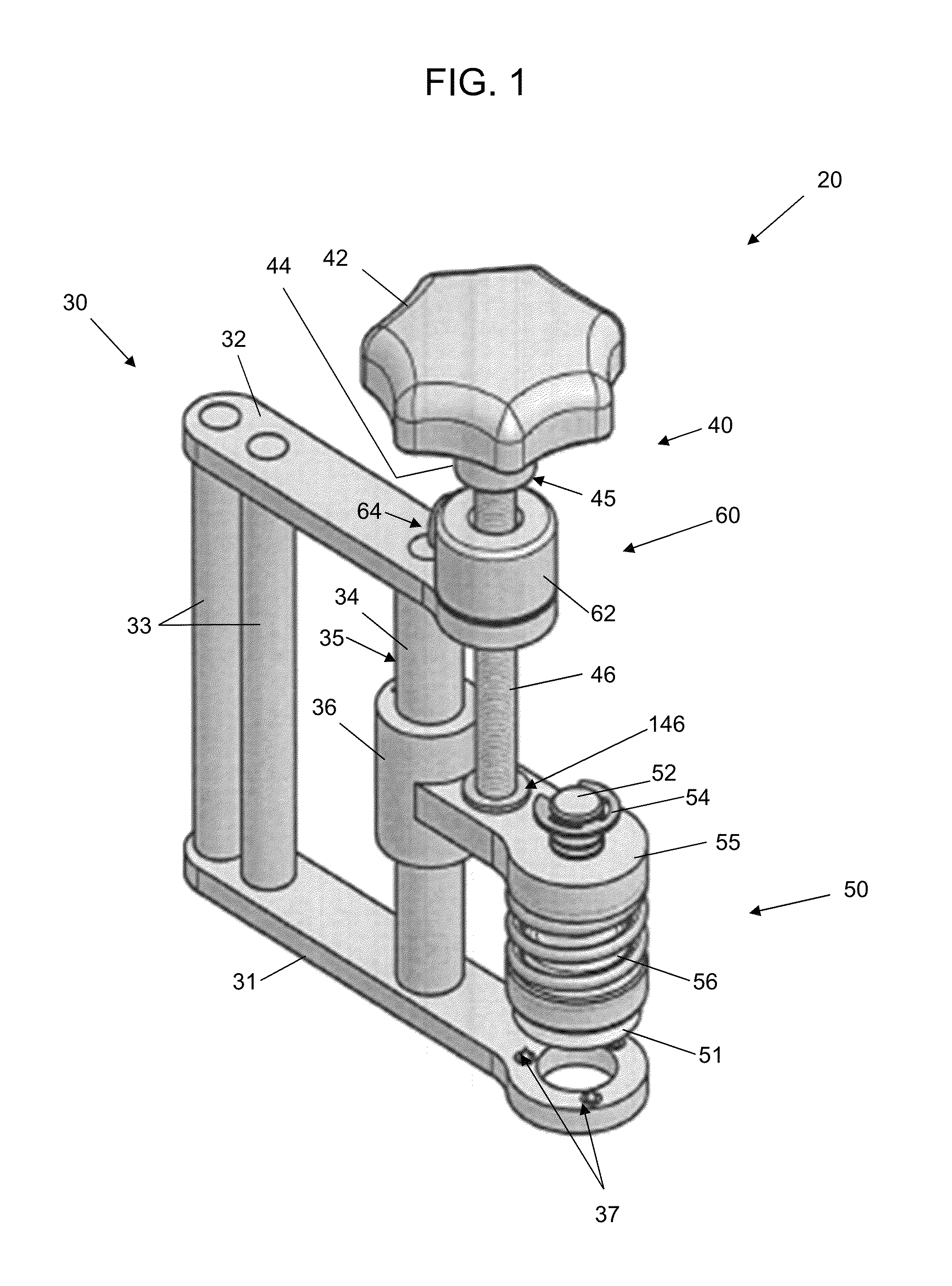
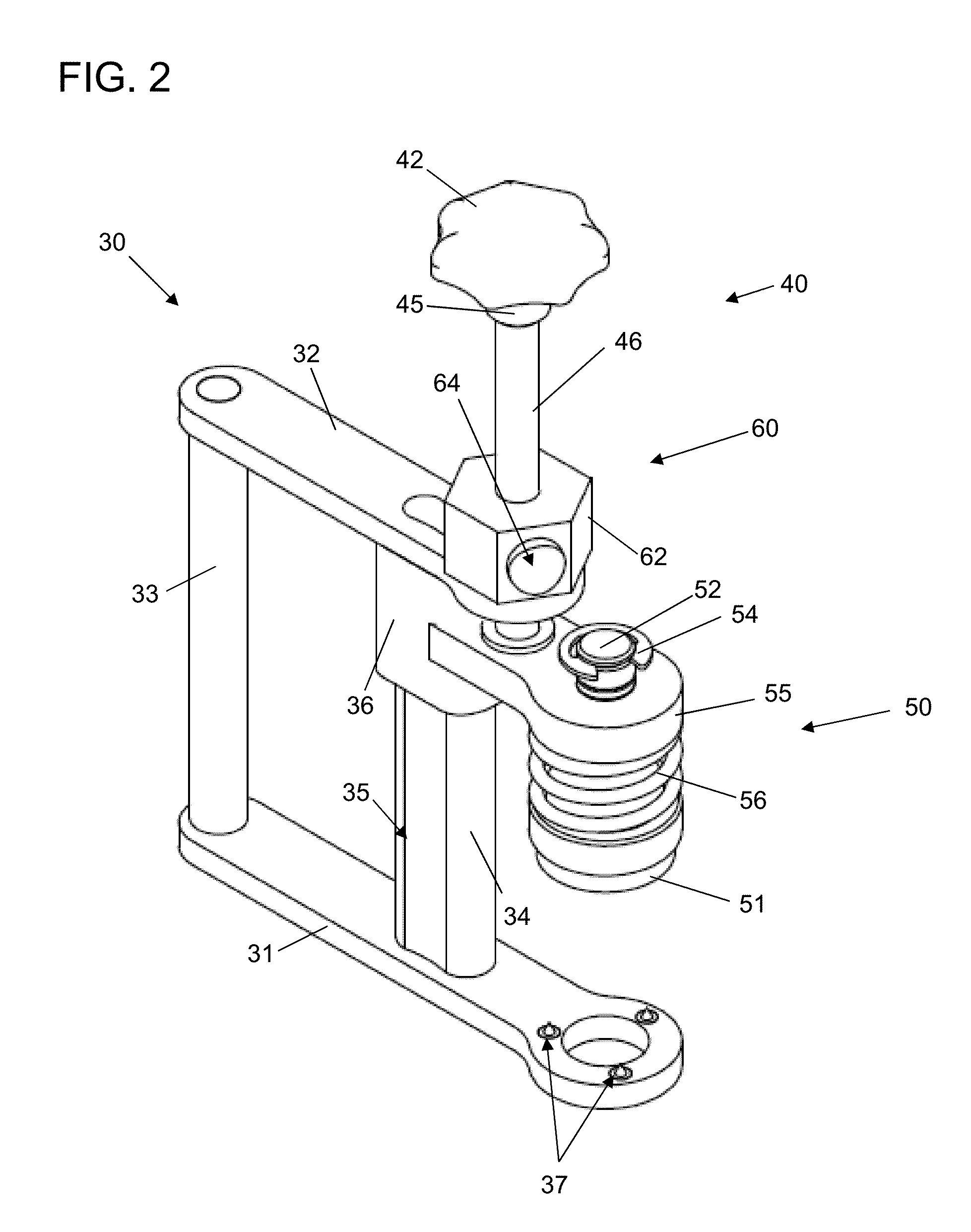
[0042]FIGS. 1 and 2 are perspective views of different embodiments of the adjustable measured applied pressure clamp device 20 for use with embodiments of the present invention. As shown in the embodiment in FIG. 1, the device 20 comprises a frame assembly 30 for receiving and maintaining a knob assembly 40 and a clamp indicating assembly 50.

[0043]The frame assembly 30 can comprise a bottom base plate 31 and a top plate 32, which are held apart in substantially parallel relation by a handle member 33 and a guide rod 34. In various embodiments, the base plate 31 includes one or more spikes 37 for use in assisting with holding an object being compressed during operation of the device associated with embodiments of the present invention. As shown in FIG. 10, openings 131 are provided in the base plate 31 to receive spikes. While the handle member 33 is shown in FIG. 1 as a pair of substantially cylindrical bodies secured to the bottom 31 and top 32 plates, it will be appreciated that t...


PUM


Abstract

Devices and methods provide for measuring applied pressure on an article, such as a patella construct during a surgical procedure. Embodiments include a clamp having an upper frame arm, a lower frame arm and a clamp assembly, and further include a clamp with a knob assembly and a pressure monitor assembly. Differently sized bushing adapters can be interchangeably employed with a clamp stem to adapt to the relative sizes of objects being clamped.

Description

FIELD[0001]The present invention relates to medical instrumentation, and more particularly to a device for facilitating the installation of an artificial prosthesis and related methods.BACKGROUND AND SUMMARY[0002]The typical known art of surgically resurfacing the natural patella, when necessary to accept an artificial patella prosthesis, requires the patella to be everted and held in a position allowing the surgeon to have access to the articulating surface which normally articulates within the intercondylar notch between the femoral condyles.[0003]The natural patella is first measured, establishing its exact thickness, after which the surgeon resects the appropriate thickness of the posterior portion of the natural patella, and then prepares the surface to receive the artificial patella prosthesis. A patella trial replicating the actual implant to be installed is placed upon the prepared patella surface to confirm proper fit and thickness of the patella construct that establishes ...

Claims


Application Information

Patent Timeline
Patent Type & Authority Patents(United States)
IPC IPC(8): A61F2/46
CPCA61F2/4657A61F2/4603A61F2/461A61B17/8802B25B5/06B25B5/101B25B5/102A61F2002/4625A61F2002/4666B25B5/163A61F2/3877A61F2/3094A61F2002/30449A61B17/8841A61F2002/4627
Inventor BOYER, JOHN STUARTANDERSON, BRUCE REED
Owner BOYER ANDERSON
Why Eureka
Try Eureka