
Method and apparatus for bending a micro-channel heat exchanger

a technology of heat exchanger and microchannel, which is applied in the direction of heat exchange apparatus, etc., can solve the problems of reducing the efficiency of heat exchanger, requiring a more difficult bending operation, and the behavior of the tubes and fins at the “corner” where the manifolds are bent, so as to reduce the crushing of the air center and tighten the radius

Inactive Publication Date: 2016-08-16
MAHLE INT GMBH
View PDF12 Cites 1 Cited by
  • Summary
  • Abstract
  • Description
  • Claims
  • Application Information

AI Technical Summary

Benefits of technology

[0007]The heat exchanger design and the method of manufacturing and apparatus disclosed control and minimize the crushing of the air centers and buckling of the refrigerant tubes when the core is bent. A portion of the tube edges on the inside of the core bend is exposed by narrowing or offsetting the corrugated fins in the bend area. The tube edge offset provides room for a corresponding set of grooved vertical braces, one for each tube edge, to engage the clear portions of the tube edges. The vertical braces are fixed in the proper orientation by a flexible backing that allows them to bend from an initial flat shape on the core face into a bend radius, matching the typical cylindrical mandrel that controls the inner radius of the bend. The improved design allows a tighter radius than a conventional bend through the refrigerant tubes and centers.

Problems solved by technology

That same U or V shaped bend of the core face can be applied to stationary air conditioning applications as well (residential heat pump, for example), but such applications often require a more difficult bending operation in which the tubes are left unbent, straight, and vertical, while the manifolds are bent into a rectangular perimeter.
The vertical tubes drain condensation better, but the manifolds are heavier and more difficult to bend.
Another issue is the behavior of the tubes and fins at the “corners” where the manifolds are bent.
These can buckle and deform, presenting at least an aesthetic objection, if not a dimunition in performance.
Fins may also pull away from the tubes in the bend area, decreasing performance.
This limits how tight or small a bend radius can be achieved.
This has the obvious drawback of removing a considerable amount of heat exchange area out of the core face, besides necessitating the addition of some sort of screen at the corners to “fill in” the missing area and avoid disturbance of the forced air flow at the paths of least resistance.
All of these represent major changes to the way in which the basic core is stacked and brazed, and are therefore very undesirable in terms of cost and productivity.
While both systems improve the bend by accommodating or absorbing the crush, neither serves to actively control the behavior and alignment of the tubes in the area of the bend.

Method used


Image

  • Method and apparatus for bending a micro-channel heat exchanger
  • Method and apparatus for bending a micro-channel heat exchanger
  • Method and apparatus for bending a micro-channel heat exchanger

Examples


Embodiment Construction

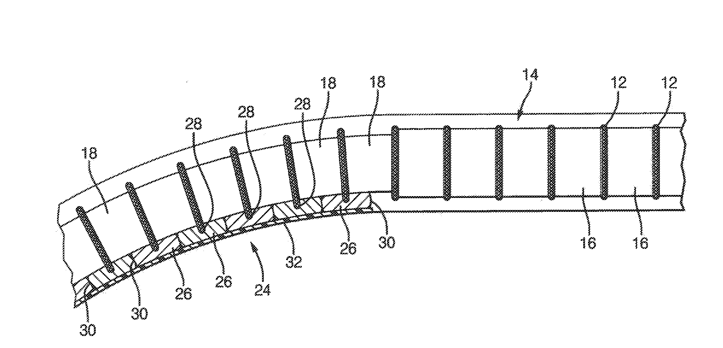
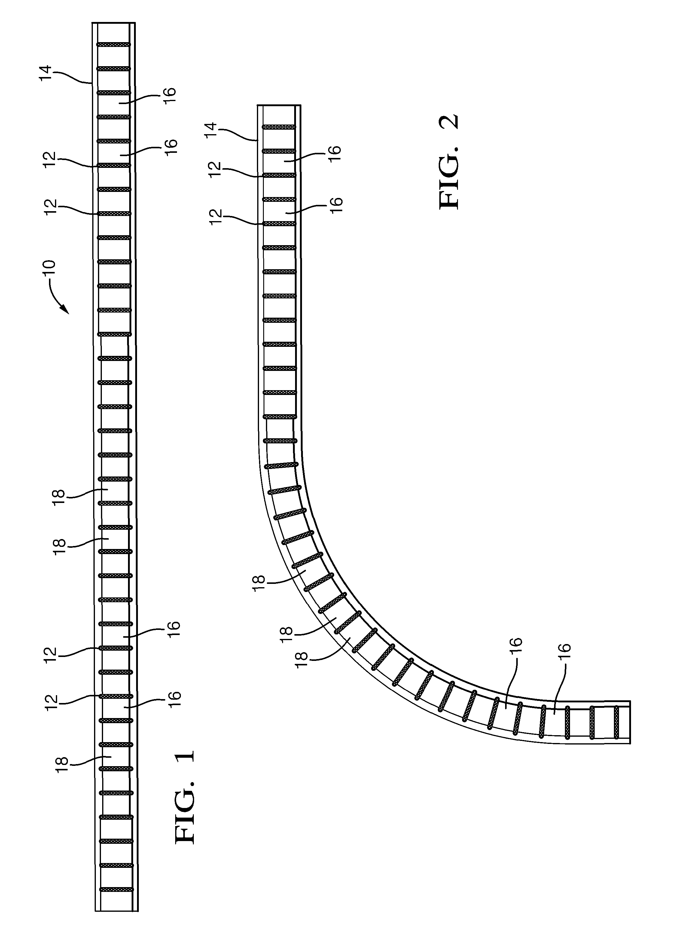
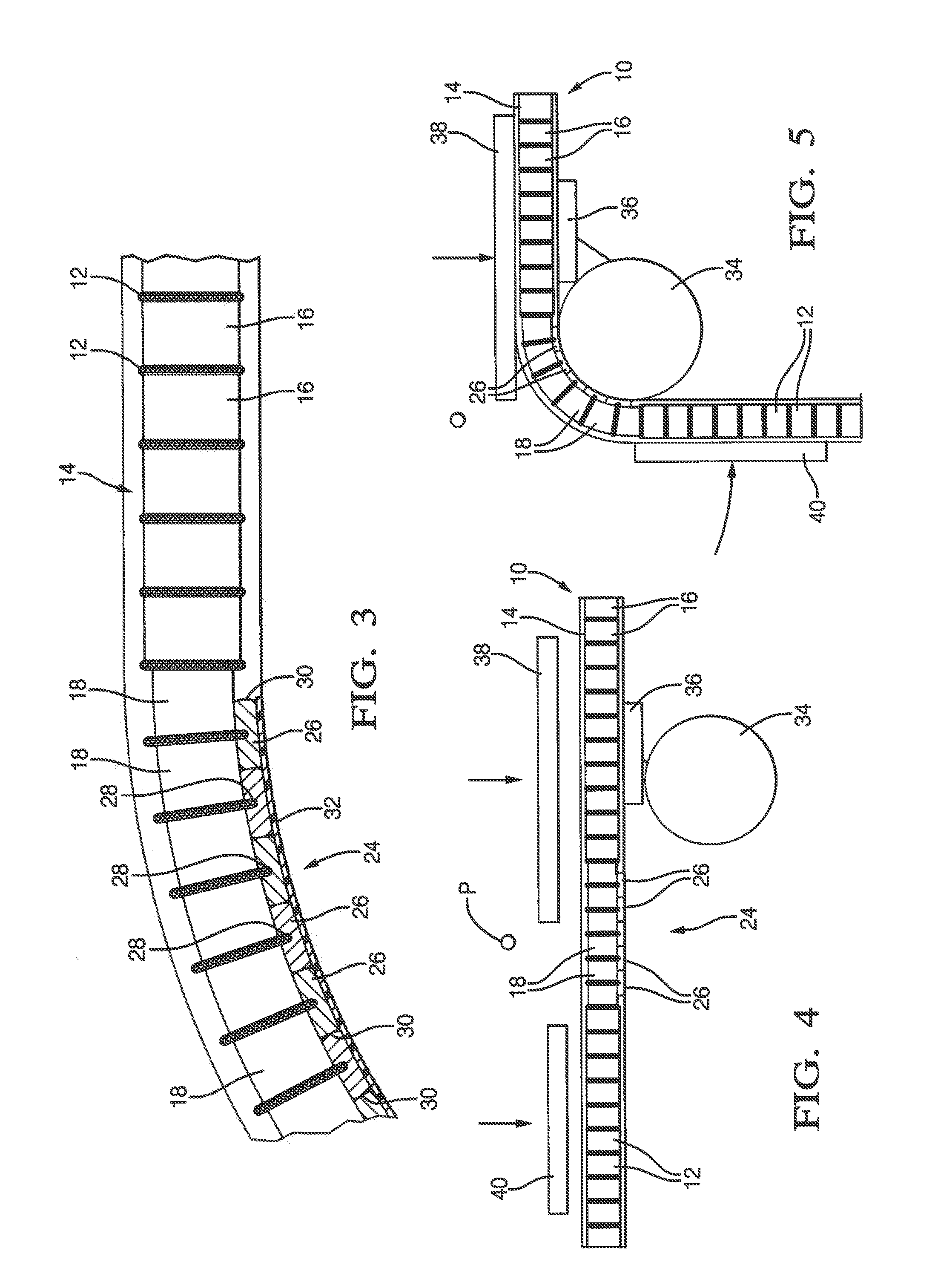
[0014]FIG. 1 shows the flat, unbent core 10, which consists of flat, parallel, regularly spaced tubes 12 extending between parallel upper and lower cylindrical manifolds 14. Only a section thereof is shown, in the area where a bend would occur, and the remainder of the core would be identical. These basic parts of the core are conventional as to size, shape and material, typically a brazable aluminum alloy. The basic core differs only as to the particular corrugated air centers or fins that are installed between the tubes 12 encompassed by and within those areas intended to be bent. Outside of the bend areas, the fins 16 are also conventional as to size, shape and installation orientation. Most significantly, those fins 16 have a width substantially equal to the depth of the tubes 12. The remaining centers 18, those installed between those tubes encompassed by the bend areas, are significantly narrower and, in this embodiment, installed centrally between the tubes 12 so as to create...


PUM

PropertyMeasurementUnit
radiusaaaaaaaaaa
areaaaaaaaaaaa
clamping forceaaaaaaaaaa

Abstract

An improved corner bending apparatus and method for a bent head exchanger includes a first step of providing a tube edge clearance to at least the inner core face edges of those few tubes encompassed by the area of the core to be bent. A series of elongated braces, able to flex relative to one another, is placed into the tube edge clearance prior to bending. The braces actively maintain the tube edges (and tubes) in a parallel, undeformed orientation during the bend, which may be done by otherwise conventional apparatus.

Description

[0001]The invention relates to a bent micro-channel heat exchanger and a method to manufacture the same. Priority is claimed to U.S. provisional application 61 / 188,439, filed Aug. 8, 2008.TECHNICAL FIELD OF INVENTIONBackground of Invention[0002]Brazed aluminum heat exchangers of the type having spaced header tanks (or manifolds), flat elongated tubes corrugated air fins or centers have been a commonplace in automotive applications, where they are of a relatively small face area and installed flat, such as air conditioning condensers. It is known to bend such automotive heat exchangers into a V or U shape, as shown in U.S. Pat. No. 4,876,778, but this is a relatively simple and straighforward bend in which the tubes and fins (core face) themselves are bent, perpendicular to the tubes, not the heavier manifolds themselves, which remain straight[0003]That same U or V shaped bend of the core face can be applied to stationary air conditioning applications as well (residential heat pump, ...

Claims


Application Information

Patent Timeline
Patent Type & Authority Patents(United States)
IPC IPC(8): B21D53/06B21D53/02B21D7/024B21D7/022
CPCB21D7/022B21D7/024B21D53/02B21D53/06Y10T29/4935
Inventor SAMUELSON, DAVID E.EDWARD, KENT S.
Owner MAHLE INT GMBH
Features
  • Generate Ideas
  • Intellectual Property
  • Life Sciences
  • Materials
  • Tech Scout
  • Unparalleled Data Quality
  • Higher Quality Content
  • 60% Fewer Hallucinations
Learn More