Eureka AIR delivers breakthrough ideas for toughest innovation challenges, trusted by R&D personnel around the world.

Container having non-linear and linear tracks for supporting movable dunnage

a technology of moving parts and containers, which is applied in the direction of transportation and packaging, packaging foodstuffs, and packaged goods. it can solve the problems of unsatisfactory delay in accessing and removing parts from containers, difficult and time-consuming removal of parts therein, and difficulty in accessing, so as to achieve efficient and safe removal, without unnecessary stress or strain on the operator

Active Publication Date: 2016-08-23
BRADFORD CO
View PDF60 Cites 3 Cited by
  • Summary
  • Abstract
  • Description
  • Claims
  • Application Information

AI Technical Summary

Benefits of technology

[0019]The container further comprises a movable shelf assembly comprising multiple components or pieces, at least one of which is movable. The shelf assembly supporting the emptied dunnage from one of the layers or levels of the container may be easily pushed rearwardly creating an opening for an operator to remove parts or products from the next lower level or layer of dunnage. An operator located at the front of the container may pull product to be emptied from the rear of the container forwardly to a more ergonomically friendly position after products suspended from dunnage at the front of the container have been unloaded or removed. Thus, a person unloading the container from the front or proximal location of the container will not have to stretch or reach to the back of the container to unload remaining product.
[0020]Similarly, a person loading the container from the front of the container need not stretch or reach to the back of the container to insert or load product into the container. The loader of the container may push the dunnage supports and associated dunnage loaded with product rearwardly and load additional product in a more ergonomically friendly position or manner. For example, after product is loaded into dunnage suspended by adjacent dunnage supports, these dunnage supports and associated dunnage are pushed rearwardly to enable the loader to load additional product. Thus, the container allows product to be more efficiently and safely removed from the container or inserted therein without unnecessary stress or strain on the operator.
[0021]The end members of the dunnage supports may be made of plastic or any other desired material. Each side of the container may have non-linear tracks along which the dunnage supports move to move dunnage supported by the dunnage supports closer to the user for loading or unloading product. Each end member may have at least one head located inside the interior of the track so the end member remains engaged with the track. The end member may have another head outside the track for preventing the dunnage material from entering the interior of the track.

Problems solved by technology

Some existing containers are difficult to access, which makes removal of the parts therein difficult and time-consuming.
Any delay in access and removal of the part from the container is undesirable.
The size and / or weight of the parts or workpieces may cause stress or strain on the line worker and, more particularly, on the back of the worker when inserting or removing parts from such a container.
Such ergonomically unfriendly movements may cause physical trauma, pain and other injuries that may lead to lost production time.
This requires space around the container which may not be available, depending on the physical layout of the plant or facility.
The length (front to back) of certain containers may be limited because the container manufacturer needs to eliminate the need for a line worker to walk around the container to remove product from inside the container.
The more containers needed to ship a predetermined number of parts, the greater the cost to the shipper.
This movement by the line worker is ergonomically unfriendly because the line worker must lean forward and bend down and lift a part or workpiece up and over a wall into the container to remove the part or workpiece from inside the container.
Similarly, when a part or workpiece must be inserted into a container, the line worker may have to lean forward and insert the part, which may be heavy, into its proper location inside the container, again experiencing ergonomically unfriendly movements.
Depending upon the number of times the line worker repeats this unnatural motion into the interior of the container, strain in the back, legs and arms may result.
The size and / or weight of the parts or workpieces may increase the strain on the line worker.
Thus, simply removing multiple parts during a work day may cause physical trauma, pain and other injuries that may lead to lost production time.

Method used


Image

  • Container having non-linear and linear tracks for supporting movable dunnage
  • Container having non-linear and linear tracks for supporting movable dunnage
  • Container having non-linear and linear tracks for supporting movable dunnage

Examples


Embodiment Construction

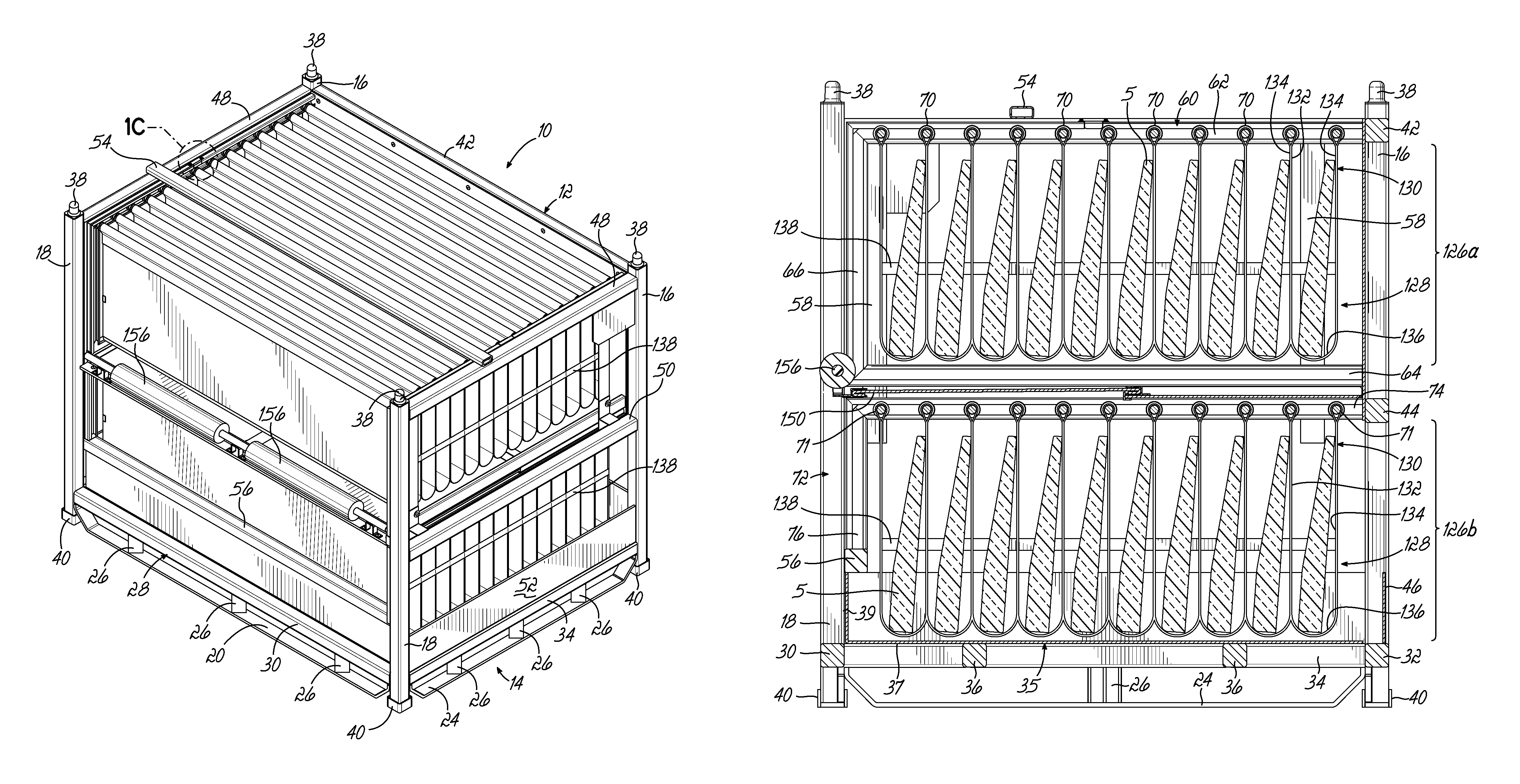
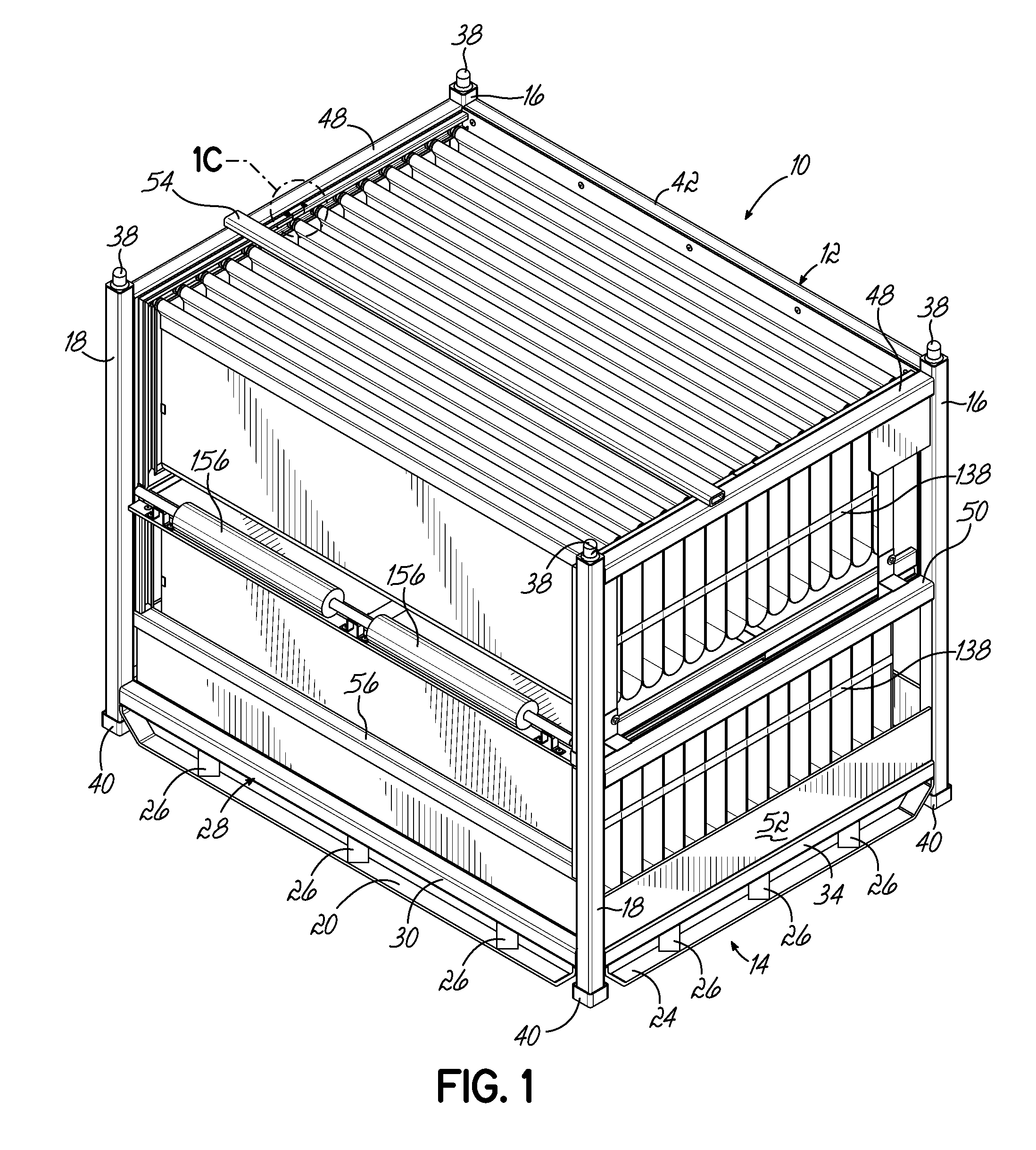
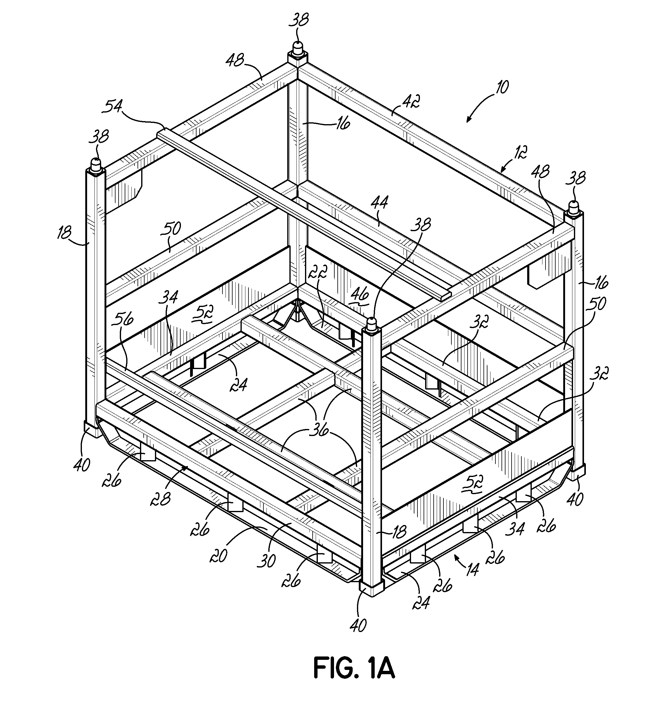
[0056]Referring to FIG. 1, there is illustrated a reusable and returnable container 10 according to one embodiment. The reusable and returnable container 10, as shown, comprises an outer metal frame 12 having a base 14, two rear corner posts 16 and two front corner posts 18, all four corner posts 16, 18 extending upwardly from the base 14.

[0057]As best shown in FIG. 1A, the base 14 is generally rectangular in shape and comprises a front perimeter member 20, a rear perimeter member 22 and two side perimeter members 24. The perimeter members of the base 14 may be secured together or secured to the corner posts 16, 18 via any conventional means, including welding. A plurality of stubs 26 extend upwardly from the base 14 and are secured thereto via any conventional means, including welding.

[0058]As best shown in FIG. 1A, a generally rectangular sub-base 28 is spaced above the base 14 by the stubs 26 and secured to the stubs 26 by any conventional means, including welding. The sub-base 2...


PUM


Abstract

A container for holding product therein during shipment and being returned for reuse has a frame, tracks supported by opposite sides of the frame, and a plurality of dunnage supports extending between the tracks. At least one of the tracks on each side is generally U-shaped and at least one is linear. Each dunnage support may comprise end members and a middle member, the end members being movable along the tracks. The dunnage supports support dunnage for supporting products for storage or shipment.

Description

CROSS REFERENCE TO RELATED APPLICATIONS[0001]This application is a continuation-in-part of U.S. patent application Ser. No. 14 / 081,439 filed Nov. 15, 2013, which is fully incorporated by reference herein.FIELD OF THE INVENTION[0002]The present invention relates to containers for use in shipping and, more particularly, to containers with movable members for supporting product.BACKGROUND OF THE INVENTION[0003]A large number of different container structures are utilized by manufacturers to ship a variety of different products to end users, which may be, for example, assembly plants. In the automobile industry, for example, an assembly plant assembling a particular automobile might utilize a number of different parts from different manufacturers. These manufacturers ship their respective parts to the assembly plant in container structures where the parts are then removed from dunnage or support members inside the container structure and assembled into a finished automobile.[0004]Access...

Claims


Application Information

Patent Timeline
Patent Type & Authority Patents(United States)
IPC IPC(8): B65D19/06B65D19/44B65D85/68
CPCB65D19/06B65D19/44B65D85/68B65D2519/00587B65D2519/00626B65D2519/00646B65D2519/00666B65D2519/00701B65D2519/00805B65D2519/0082B65D2519/009B65D2519/0097B65D2585/6882B65D2585/6887B65D2519/00024B65D2519/00034B65D2519/00059B65D2519/00069B65D2519/00164B65D2519/00174B65D2519/00233B65D2519/00243B65D2519/00273B65D2519/00288B65D2519/00323B65D2519/00333B65D2519/00373B65D2519/00497B65D2519/00502B65D2519/00532B65D2519/00562B65D2519/00094B65D2519/00293B65D81/05B65D19/02B65D88/546B65D90/008B65D90/12
Inventor BUBLITZ, TIMOTHY A.FEENSTRA, MARK J.BURNS, ALLEN L.
Owner BRADFORD CO
Why Eureka
Eureka Blog
Learn More