Container Having At Least One Lockable Crossbar Assembly Movable Along Tracks

a technology of lockable crossbar and container, which is applied in the direction of transportation and packaging, packaging foodstuffs, and packaged goods, etc., can solve the problems of unsatisfactory delay in accessing and removing parts from containers, difficult and time-consuming removal of parts therein, and difficulty in accessing, so as to achieve efficient and safe removal, without unnecessary stress or strain on the operator

Active Publication Date: 2017-11-02
BRADFORD CO
View PDF3 Cites 1 Cited by
  • Summary
  • Abstract
  • Description
  • Claims
  • Application Information

AI Technical Summary

Benefits of technology

[0026]Due to the tracks, movable dunnage supports and dunnage supported thereby, a person loading the container from the front of the container need not stretch or reach to the back of the container to insert or load product into the container. The loader of the container may push the dunnage supports and associated dunnage loaded with product rearwardly and load additional product in a more ergonomically friendly position or manner. For example, after product is loaded into dunnage suspended by adjacent dunnage supports, these dunnage supports and associated dunnage are pushed rearwardly to enable the loader to load additional product. Thus, the container allows product to be more efficiently and safely removed from the container or inserted therein without unnecessary stress or strain on the operator.

Problems solved by technology

Some existing containers are difficult to access, which makes removal of the parts therein difficult and time-consuming.
Any delay in access and removal of the part from the container is undesirable.
However, the installation of such turntables adds to the cost of production, takes up valuable floor space and reduces plant flexibility.
The size and / or weight of the parts or workpieces may cause stress or strain on the line worker and, more particularly, on the back of the worker when inserting or removing parts from such a container.
Such ergonomically unfriendly movements may cause physical trauma, pain and other injuries that may lead to lost production time.
This requires space around the container which may not be available, depending on the physical layout of the plant or facility.
The length (front to back) of certain containers may be limited because the container manufacturer needs to eliminate the need for a line worker to walk around the container to remove product from inside the container.
The more containers needed to ship a predetermined number of parts, the greater the cost to the shipper.
This movement by the line worker is ergonomically unfriendly because the line worker must lean forward and bend down and lift a part or workpiece up and over a wall of the container to remove the part or workpiece from inside the container.
Similarly, when a part or workpiece must be inserted into a container, the line worker may have to lean forward and insert the part, which may be heavy, into its proper location inside the container, again experiencing ergonomically unfriendly movements.
Depending upon the number of times the line worker repeats this unnatural motion into the interior of the container, strain in the back, legs and arms may result.
The size and / or weight of the parts or workpieces may increase the strain on the line worker.
Thus, simply removing multiple parts during a work day may cause physical trauma, pain and other injuries that may lead to lost production time.
However, in some applications, a door is not desirable.
In these and other containers, when the container is empty or partially empty of products, the movable dunnage supports, and dunnage suspended by them, may undesirably move inside the container during shipment, possibly creating noise and potentially damaging a portion of the container.

Method used


Image

  • Container Having At Least One Lockable Crossbar Assembly Movable Along Tracks
  • Container Having At Least One Lockable Crossbar Assembly Movable Along Tracks
  • Container Having At Least One Lockable Crossbar Assembly Movable Along Tracks

Examples


Embodiment Construction

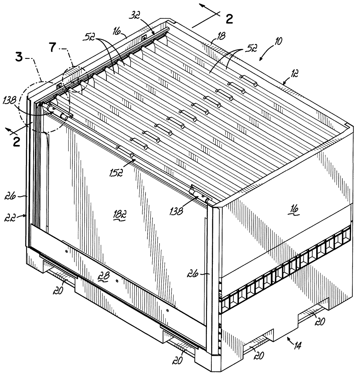
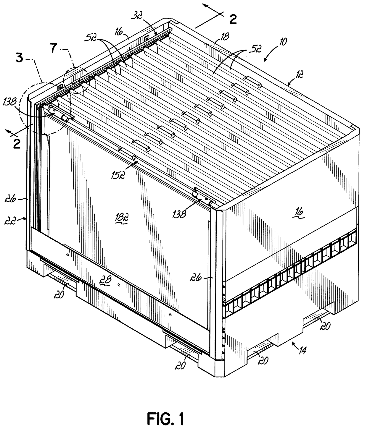
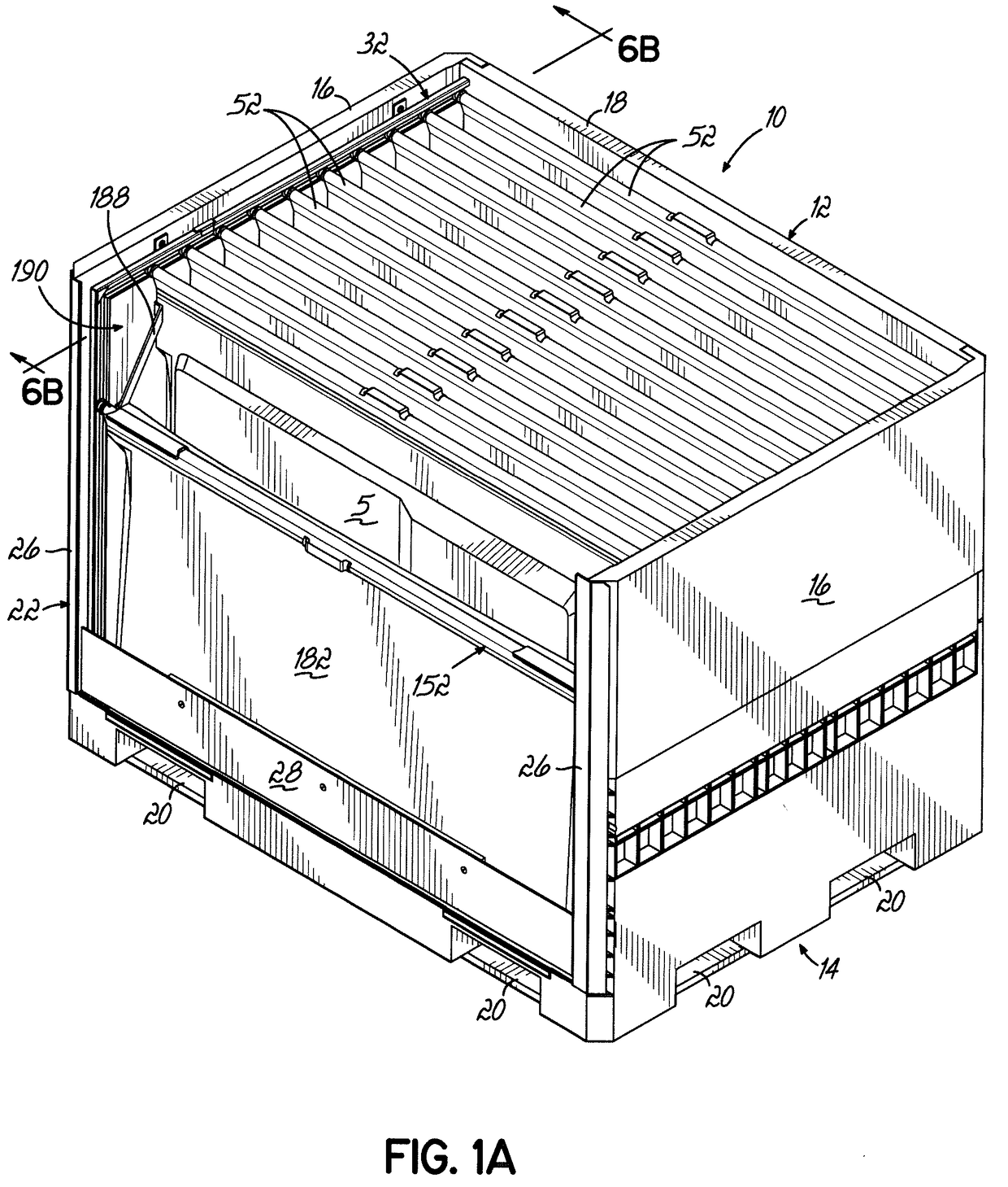
[0099]Referring to FIG. 1, there is illustrated a reusable and returnable container 10 for holding products 5 therein, according to one embodiment. The reusable and returnable container 10, as shown, comprises a body 12 having a base 14, side walls 16 and a rear wall 18, all extending upwardly from the base 14. The side walls 16 and / or rear wall 18 may be hingedly secured to the base 12. The base 14 may have a plurality of passages 20 therethrough adapted to receive the prongs of a forklift for purposes of lifting and moving the reusable and returnable container 10. Although one configuration of reusable and returnable container in the form of a pallet box is illustrated, the present invention may be used with other types or configurations of containers.

[0100]Although one specific shape of product 5 is illustrated in the drawings, this document is not intended to limit in any way the size, shape or configuration of products 5 shipped or stored in any of the embodiments described or ...


PUM


Abstract

A container for holding product therein during shipment and being returned for reuse has at least one track supported by each side of the container. The container has dunnage supports extending between corresponding tracks at the same level. At least one lockable crossbar assembly has one or more locking assemblies to fix the position of the lockable crossbar assembly relative to the tracks. Dunnage may hang from the dunnage supports for supporting products during storage or shipment.

Description

CROSS REFERENCE TO RELATED APPLICATIONS[0001]This application claims the benefit of U.S. Provisional Patent Application Ser. No. 62 / 364,057 filed Jul. 19, 2016 and the benefit of U.S. Provisional Patent Application Ser. No. 62 / 328,683 filed Apr. 28, 2016. Both applications are fully incorporated by reference herein.FIELD OF THE INVENTION[0002]The present invention relates to containers for use in shipping and, more particularly, to containers with at least one lockable crossbar assembly for maintaining dunnage supports and dunnage in a desired location.BACKGROUND OF THE INVENTION[0003]Different container structures are utilized by manufacturers to ship a variety of different products to end users, which may be, for example, assembly plants. In the automobile industry, for example, an assembly plant assembling a particular automobile might utilize a number of different parts from different manufacturers. These manufacturers ship their respective parts to the assembly plant in contain...

Claims


Application Information

Patent Timeline
Patent Type & Authority Applications(United States)
IPC IPC(8): B65D88/54B65D81/02B65D25/00B65D25/04B65D90/12B65D88/12
CPCB65D88/546B65D25/04B65D88/12B65D81/022B65D90/12B65D25/005B65D19/44B65D85/68B65D2585/6887B65D19/06B65D19/18B65D2519/00024B65D2519/00034B65D2519/00059B65D2519/00069B65D2519/00094B65D2519/00174B65D2519/00233B65D2519/00273B65D2519/00293B65D2519/00323B65D2519/00333B65D2519/00338B65D2519/00373B65D2519/00422B65D2519/00532B65D2519/00562B65D2519/00621B65D2519/00666B65D2519/00701B65D2519/00805B65D2519/0081B65D2519/0082B65D2519/0097B65D81/05Y02W30/80
Inventor BRADFORD, JUDSON A.BURNS, ALLEN L.SANGER, MATTHEW S.
Owner BRADFORD CO
Why Eureka
Try Eureka