Structure intended to hold an electric battery for powering an electric motor for driving a motor vehicle

Active Publication Date: 2016-10-11
RENAULT SAS
View PDF12 Cites 2 Cited by
  • Summary
  • Abstract
  • Description
  • Claims
  • Application Information

AI Technical Summary

Benefits of technology

The patent aims to provide a structure that can hold an electric battery and prevent it from damage during a side collision with a motor vehicle. The new structure is designed to be simple, reliable, and robust to provide better protection for the battery.

Problems solved by technology

A crack in the battery casing is acceptable, but it must not exceed a certain size guaranteeing that it is impossible for a user to pass a finger through it.
In certain cases, its installation between the two axles of the vehicle makes it vulnerable to collision, especially to a perpendicular side collision against a pole.

Method used


Image

  • Structure intended to hold an electric battery for powering an electric motor for driving a motor vehicle
  • Structure intended to hold an electric battery for powering an electric motor for driving a motor vehicle
  • Structure intended to hold an electric battery for powering an electric motor for driving a motor vehicle

Examples


Embodiment Construction

[0023]An embodiment of motor-vehicle chassis 1 is described hereinafter with reference to FIGS. 1 and 2.

[0024]The chassis is in particular an electric or hybrid motor-vehicle chassis, especially a chassis of a four-wheel electric vehicle.

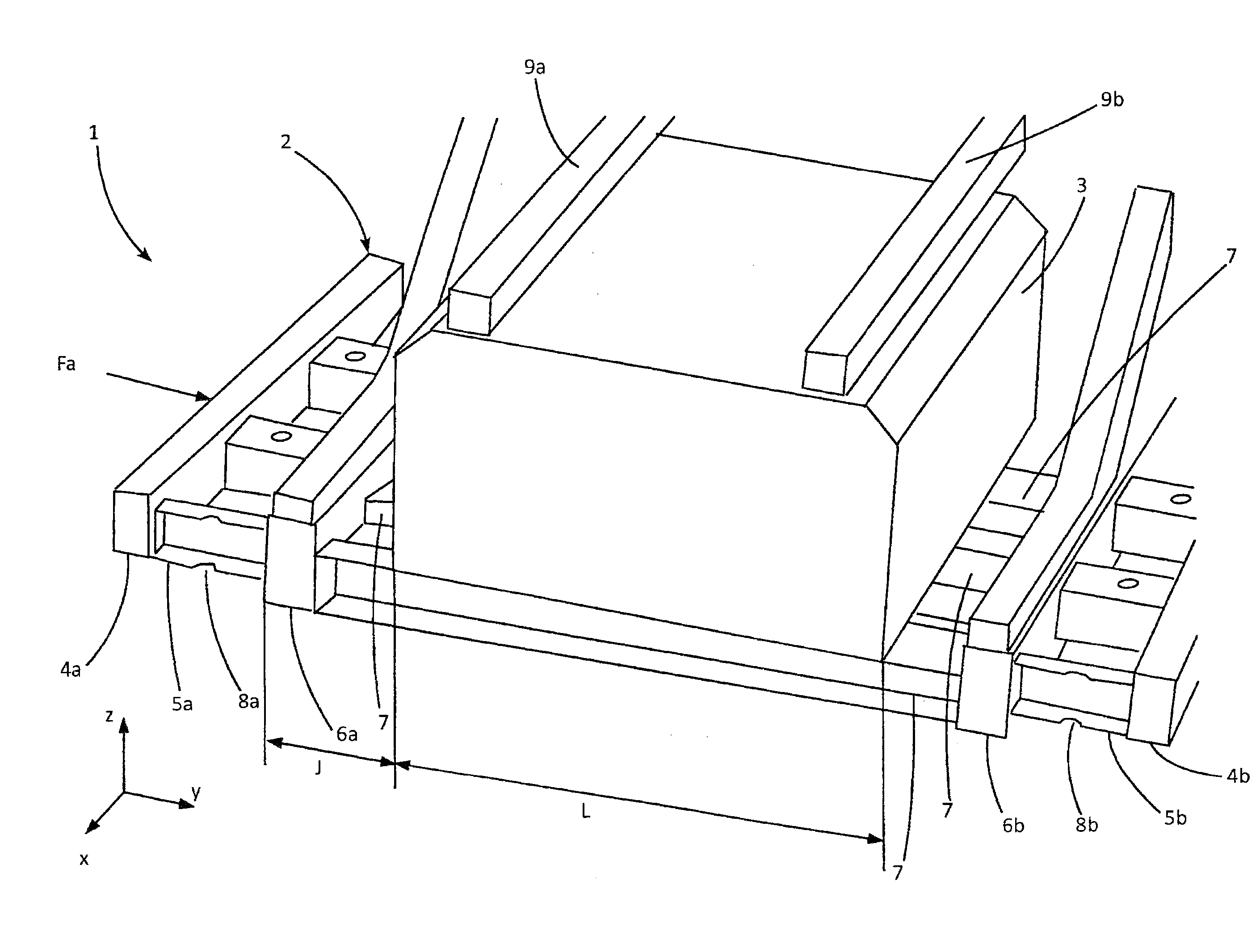
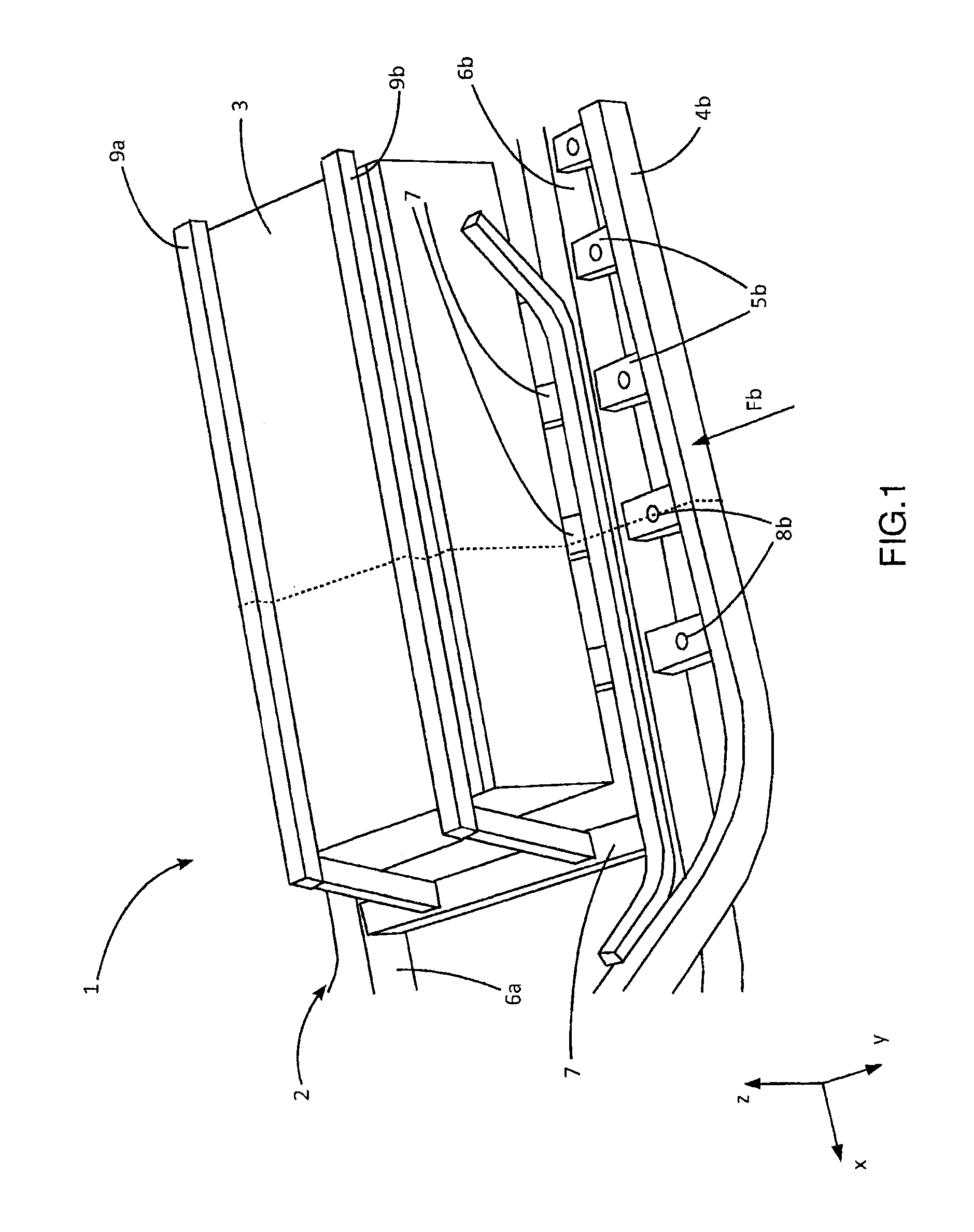
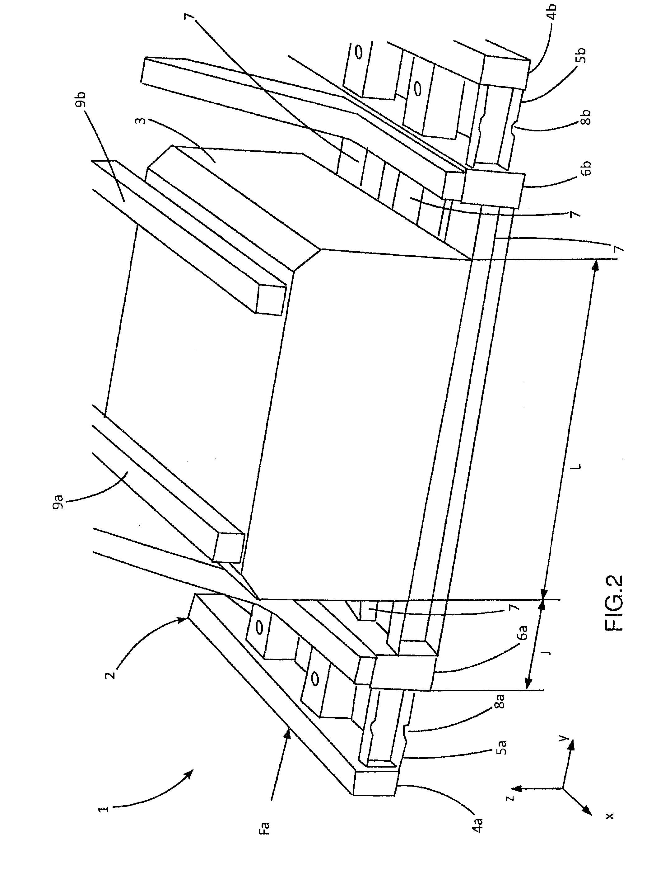
[0025]The chassis comprises, preferably in its middle part, a structure 2 intended to hold an electric battery 3, especially to hold an electric battery for powering an electric drive motor for the motor vehicle.

[0026]The chassis extends in longitudinal direction x, wherein this longitudinal direction is that of displacement of the vehicle in a straight line. The transversal direction perpendicular to the longitudinal direction is marked y and the vertical direction perpendicular to the two foregoing directions is marked z.

[0027]The structure comprises:[0028]a rigid element 7, 6a, 6b, above which the battery is intended to be disposed; and[0029]energy-absorbing elements 4a, 5a, 4b, 5b, disposed laterally on both sides of the rigid element.

[0030]Pref...


PUM


Abstract

A structure configured to hold an electric battery for powering an electric motor, or to hold an electric battery for powering an electric motor for driving a motor vehicle, the structure including a rigid element, above and / or below which the battery is configured to be located, and, laterally on either side of the rigid element, energy absorbing elements, the energy absorbing elements including deformable members that extend at least approximately in a lateral direction.

Description

BACKGROUND[0001]The present invention relates to a structure intended to hold an electric battery, especially an electric battery for powering an electric drive motor for a motor vehicle. It also relates to a chassis of a motor vehicle having such a structure. Finally, it relates to a motor vehicle comprising such a structure or such a chassis.[0002]Certain motor vehicles, such as electric or hybrid vehicles, comprise an electric battery for powering an electric drive motor. For safety concerns, it is necessary to be sure of the integrity of the electric battery for powering the motor in different collision configurations:[0003]Head-on collision;[0004]Rear-end collision;[0005]Side collision against a pole.[0006]The objective is to avoid any electric shock and / or any short circuit capable of generating a fire during or after a collision. To achieve this, it is necessary to guarantee the integrity of the battery casing and to prevent any possibility of contact with its internal elemen...

Claims


Application Information

Patent Timeline
IPC IPC(8): H01M2/10B62D21/15B60K1/04B60L11/18H01M50/242
CPCB62D21/157B60K1/04B60L11/1877H01M2/1083B60K2001/0438Y02T10/7005Y02T10/705B60L50/66Y02T10/70Y02E60/10H01M50/242
Inventor LE JAOUEN, GUILLAUMEMAHE, CYRILLELE DUC, FRANCOIS
Owner RENAULT SAS
Why Eureka
Try Eureka