Polarization maintaining connectors

a technology of maintaining connectors and polarization, applied in the direction of optics, instruments, optical light guides, etc., can solve the problems of uncontrolled cross coupling of energy between modes, interaction and cross coupling, and the difficulty of inducing cross coupling via external stress applications, so as to facilitate interengagement, minimize angular offset, and minimize angular offset

Active Publication Date: 2016-10-18
TYCO ELECTRONICS LOGISTICS AG (CH)
View PDF30 Cites 17 Cited by
  • Summary
  • Abstract
  • Description
  • Claims
  • Application Information

AI Technical Summary

Benefits of technology

[0011]The present invention relates to a connector in which the polarization axis of the PM fiber is aligned to a keying element of a connector, such that similar connectors can mate with minimal angular offset. In one embodiment, different components of the connector are keyed with difference clearances, leading to very tightly toleranced keying at the ferrule containing the PM fiber to minimize angular offset. More specifically, the outer components of the connector have one or more relatively rough keying mechanisms, which align the components sufficiently such that a finer keying mechanism associated with the ferrule can engage and thereby align the PM fibers. This way, the coarse keying mechanisms serve to “pre-align” the components, and facilitate the interengagement of the finer keying elements to precisely align the ferrule within the connector.

Problems solved by technology

Theoretically, these two modes are functionally identical, however, any deviation from a straight non-stressed fiber having perfect geometry will cause interaction and cross coupling between the two propagating modes.
Thus, for any practical setup outside of a controlled laboratory environment, use of a regular single mode fiber will result in an uncontrolled energy cross coupling between the modes, an effect which is called birefringence.
Short fiber lengths are preferred due to the relative high cost of PM cables but also because they tend to have higher attenuation than regular single mode fibers.
The more birefringence that is generated, the more stress is applied to the core, and the larger the velocity difference is between the two modes, and the more difficult it is to induce cross-coupling via external stress applications.

Method used


Image

  • Polarization maintaining connectors
  • Polarization maintaining connectors
  • Polarization maintaining connectors

Examples


Embodiment Construction

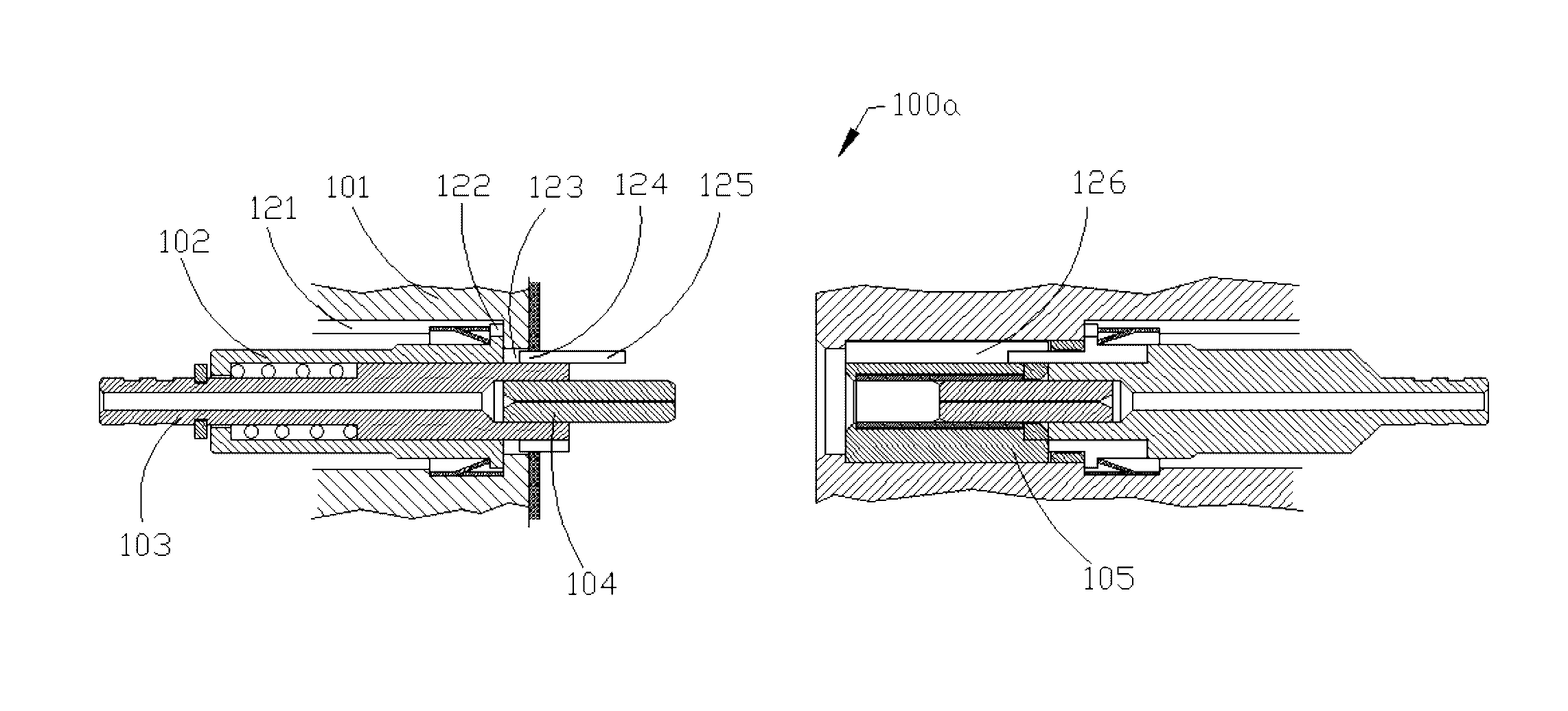
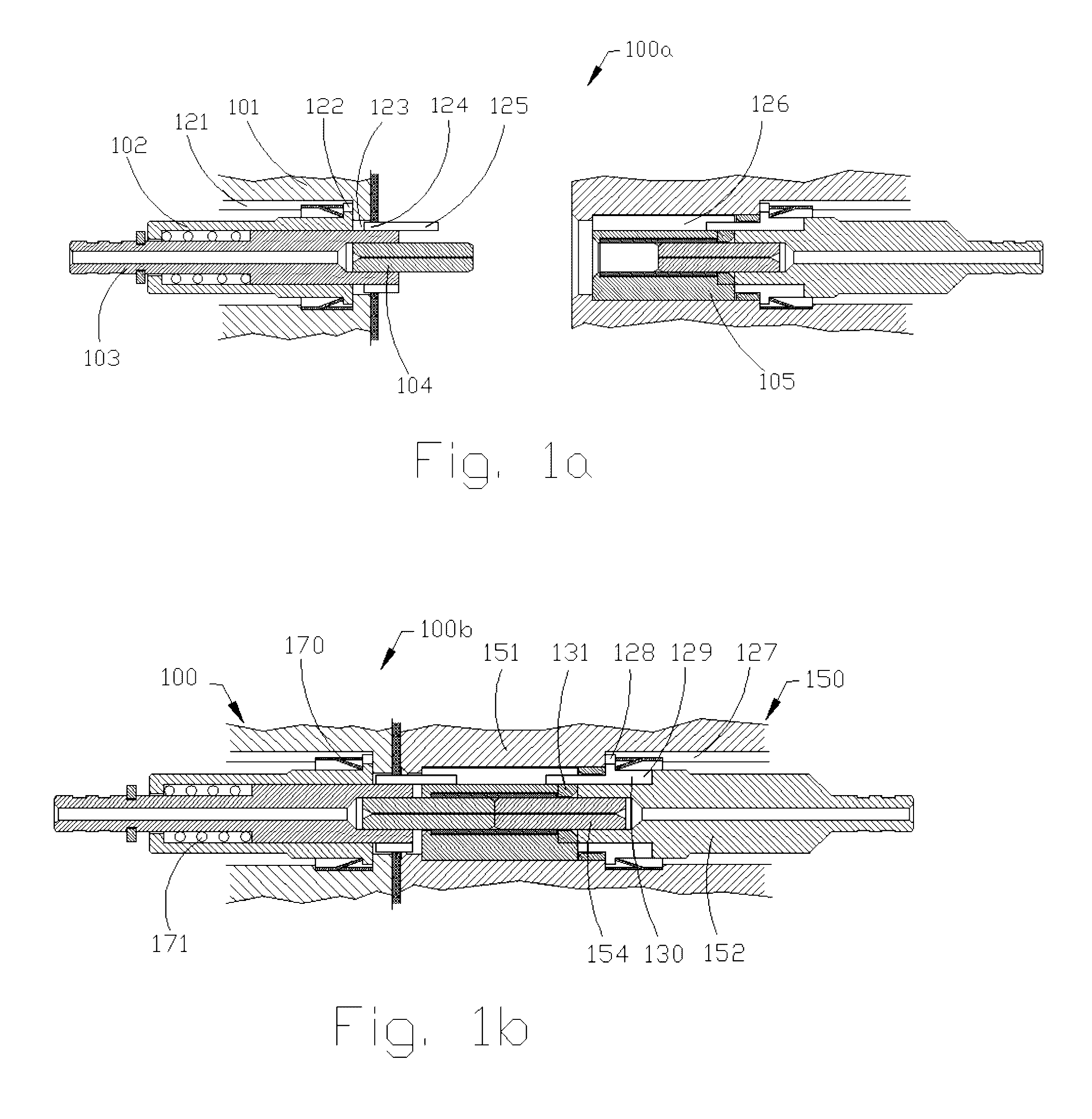
[0021]Referring to FIGS. 1a and 1b, one embodiment of the connector 100 in its unmated and mated state, 100a, 100b, respectively, is shown. The connector 100 comprises an outer housing 101 having a first keying element 121, and an inner housing 102 at least partially disposed in the outer housing 101. The inner housing comprises second and third keying elements, 122, 123. The second keying element 122 cooperates with the first keying element 121 to align angularly the inner housing 102 within the outer housing 101. The connector also comprises a ferrule assembly 103 at least partially disposed in the inner housing 102 and having a ferrule 104 and fourth and fifth keying elements 124, 125. The fourth keying element 124 cooperates with the third keying element 123 to align angularly the ferrule assembly 103 with the inner housing 102. The connector also comprises an alignment member 105 receiving at least a portion of the ferrule 104. The alignment member 105 has a sixth keying elemen...


PUM


Abstract

A connector comprising an outer housing having a first keying element, an inner housing at least partially disposed in the outer housing and having second and third keying elements, the second keying element cooperating with the first keying element to align angularly the inner housing with the outer housing, a ferrule assembly at least partially disposed in the inner housing and having a ferrule and fourth and fifth keying elements, the fourth keying element cooperating with the third keying element to align angularly the ferrule assembly with the inner housing, an alignment member receiving at least a portion of the ferrule assembly, the alignment member having a sixth keying element to cooperate with the fifth keying element to align angularly the ferrule assembly with the alignment member, and wherein the clearance between the fifth and sixth keying elements is less than that between the first and second keying elements, and between the third and fourth keying elements.

Description

FIELD OF INVENTION[0001]The present invention relates generally to polarization maintaining connectors, and, more particularly to ruggedized optical connectors for polarization maintaining fibers.BACKGROUND OF INVENTION[0002]Optical fiber connectors are a critical part of essentially all optical fiber communication systems. For instance, such connectors are used to join segments of fiber into longer lengths, to connect fiber to active devices, such as radiation sources, detectors and repeaters, and to connect fiber to passive devices, such as switches, multiplexers, and attenuators. The principal function of an optical fiber connector is to hold the fiber end such that the fiber's core is axially aligned with an optical pathway of the mating structure. This way, light from the fiber is optically coupled to the optical pathway.[0003]A light wave propagating in a standard single mode fiber has a fundamental propagation mode (TEM00), which is a combination of two, orthogonally-polarize...

Claims


Application Information

Patent Timeline
Patent Type & Authority Patents(United States)
IPC IPC(8): G02B6/38G02B6/27
CPCG02B6/3812G02B6/387G02B6/3821G02B6/3831G02B6/3882G02B6/2793G02B6/3843G02B6/3851G02B6/3871G02B6/3874G02B6/3894
Inventor GRINDERSLEV, SOREN
Owner TYCO ELECTRONICS LOGISTICS AG (CH)
Why Eureka
Try Eureka