Interconnected phalanges for robotic gripping

a technology of robotic gripping and interconnected phalanges, which is applied in the direction of gripping heads, manipulators, program-controlled manipulators, etc., can solve the problems of inability to easily configure the relationship between phalange interaction and movement in such multi-bar linkages, and the failure of multi-bar linkages known in the art to provide stiffness or rigidity in certain directions. , to achieve the effect of limiting the range of backwards

Active Publication Date: 2016-11-15
TOYOTA JIDOSHA KK
View PDF25 Cites 3 Cited by
  • Summary
  • Abstract
  • Description
  • Claims
  • Application Information

AI Technical Summary

Benefits of technology

[0008]The contact-distal pivot or rotation connection may be a gear connection. The gear connection may include a plurality of intermediary gears connected to the second end portion of the contact phalange and the first end portion of the distal phalange. The second end portion of the contact phalange may have a gear surface in direct contact with a gear surface of the first end portion of the distal phalange. An electromechanical actuator may rotate the proximal phalange. The contact phalange does not rotate when there is no contact between the contact phalange and an object. A mechanical stop limits the range of backwards and forwards rotation motion of the distal phalange. The mechanical stop maintains the distal phalange in an extended position when the distal phalange, but not the contact phalange, contacts an object. The actuator may rotate the proximal phalange in a third direction such that the rotation of the contact phalange in the first direction, the rotation of the distal phalange in the second direction, and the rotation of the proximal phalange in the third direction are in equilibrium to allow the interconnected phalanges to grip the object.

Problems solved by technology

However, the multi-bar linkages known in the art require a high number of components in addition to a high number of actuation points.
Furthermore, ratio of phalange interaction and movement in such multi-bar linkages cannot be easily configured.
Multi-bar linkage mechanisms known in the art also fail to provide stiffness or rigidity in certain directions, for example, for pushing or pressing interactions using a distal phalange.

Method used


Image

  • Interconnected phalanges for robotic gripping
  • Interconnected phalanges for robotic gripping
  • Interconnected phalanges for robotic gripping

Examples


Embodiment Construction

[0039]Apparatus, systems and methods that implement the embodiments of the various features of the present application will now be described with reference to the drawings. The drawings and the associated descriptions are provided to illustrate some embodiments of the present application and not to limit the scope of the present application. Throughout the drawings, reference numbers are re-used to indicate correspondence between referenced elements.

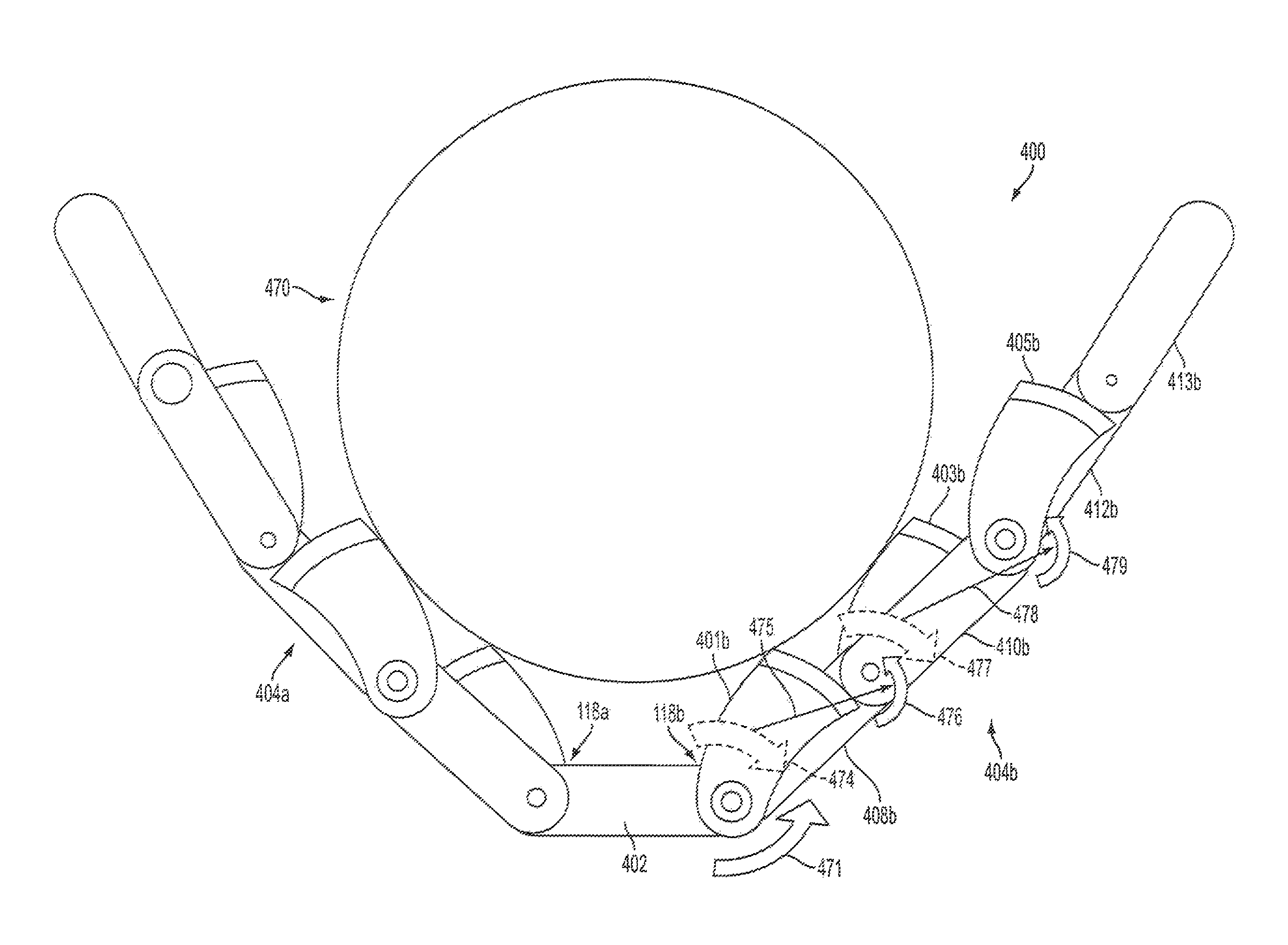
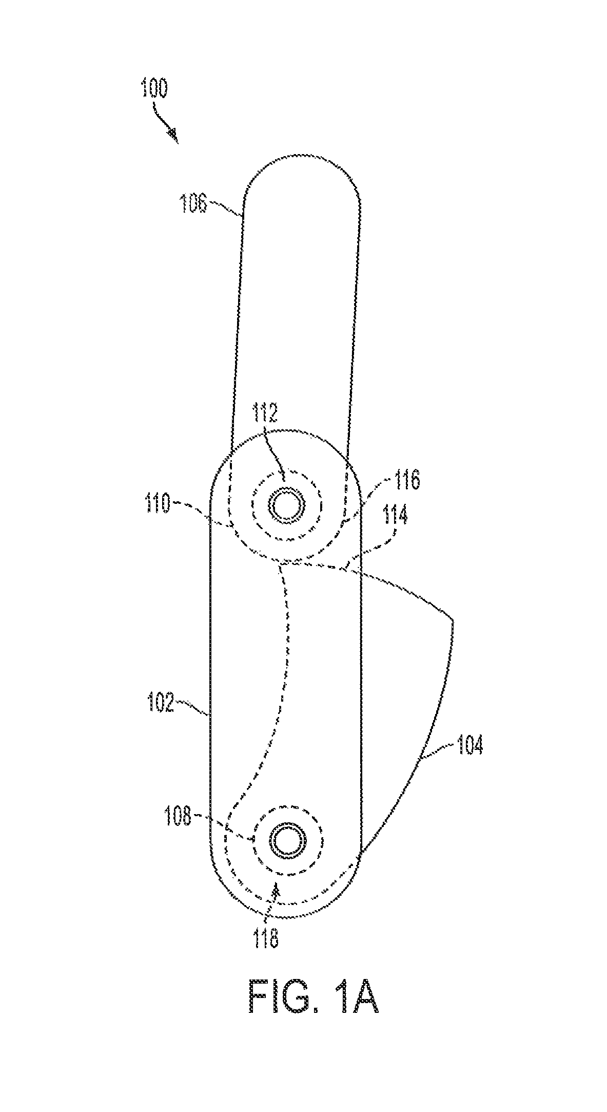
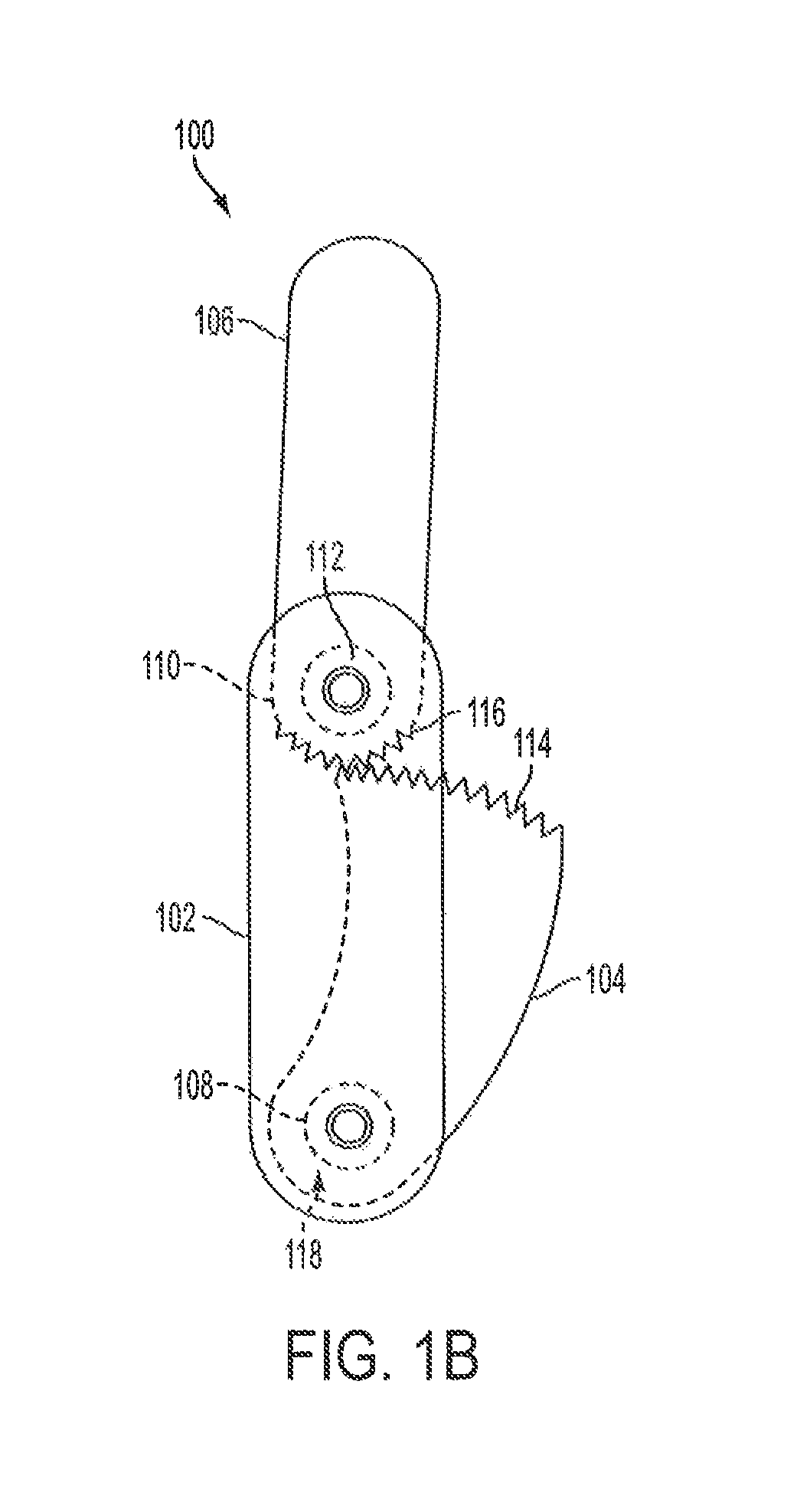
[0040]The present invention relates to a robotic gripping device that allows for pinch and power grasps using configurable connections between interconnected phalanges. The robotic gripping device includes a proximal phalange, a contact phalange, and a distal phalange that are all interconnected. The contact phalange may have a gear connection with the distal phalange and can rotate independent of the proximal phalange. The contact phalange can pivot around the same point as the proximal phalange or can pivot from any other point along t...


PUM


Abstract

A robotic gripping device allows for pinch and power grasps using interconnected phalanges with configurable connections. A distal phalange is rotatably connected to a proximal phalange. A contact phalange is rotatably connected to the proximal phalange. The contact phalange is rotatably connected to the distal phalange via a contact-distal pivot or rotation connection. In response to sufficient contact between the contact phalange and an object, the contact phalange is configured to rotate in a first direction toward the proximal phalange. The rotation of the contact phalange causes rotation of the distal phalange in a second direction toward the object. The contact-distal connection may be a configurable gear connection for adjusting the movement ratio of the contact and distal phalanges.

Description

BACKGROUND[0001]1. Field[0002]The present invention relates to robotic gripping devices and methods of controlling and operating the robotic gripping devices.[0003]2. Description of the Related Art[0004]Robotic gripping devices have been used in various applications to interact with the surrounding environment and objects therein. Multi-bar linkages have been utilized in robotic fingers for gripping or pinching an object. However, the multi-bar linkages known in the art require a high number of components in addition to a high number of actuation points. Furthermore, ratio of phalange interaction and movement in such multi-bar linkages cannot be easily configured. Multi-bar linkage mechanisms known in the art also fail to provide stiffness or rigidity in certain directions, for example, for pushing or pressing interactions using a distal phalange.[0005]Thus, there is a need for a simplified solution for robotic gripping with reduced number of components and actuation points. Further...

Claims


Application Information

Patent Timeline
Patent Type & Authority Patents(United States)
IPC IPC(8): B25J15/00B25J9/14
CPCB25J15/0009B25J9/142Y10S901/39
Inventor MOORE, DOUGLAS A.
Owner TOYOTA JIDOSHA KK
Why Eureka
Try Eureka