Image display apparatus

a technology of image display and display screen, which is applied in the field of image display screen, can solve the problems of difficult observation of the display image, bleeding of colors comparable with chromatic aberration, etc., and achieve the effect of reducing chromatic aberration

Inactive Publication Date: 2005-07-26
MINOLTA CO LTD
View PDF7 Cites 93 Cited by
  • Summary
  • Abstract
  • Description
  • Claims
  • Application Information

AI Technical Summary

Benefits of technology

[0007]An object of the present invention is to provide an image display apparatus that presents high-quality ima...

Problems solved by technology

However, a holographic optical element used as a combiner in an eyepiece optical system has a narrow range of angle selectivity, and therefore, in a conventional see-through-type image disp...

Method used


Image

  • Image display apparatus
  • Image display apparatus
  • Image display apparatus

Examples


sixth embodiment (

FIGS. 13 and 14)

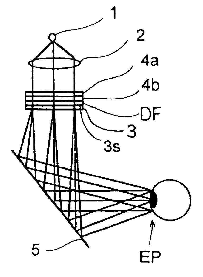
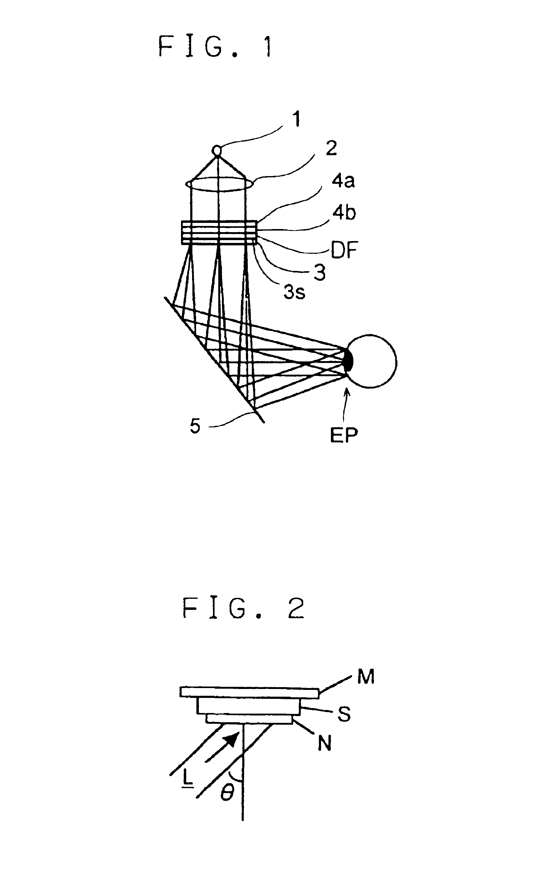
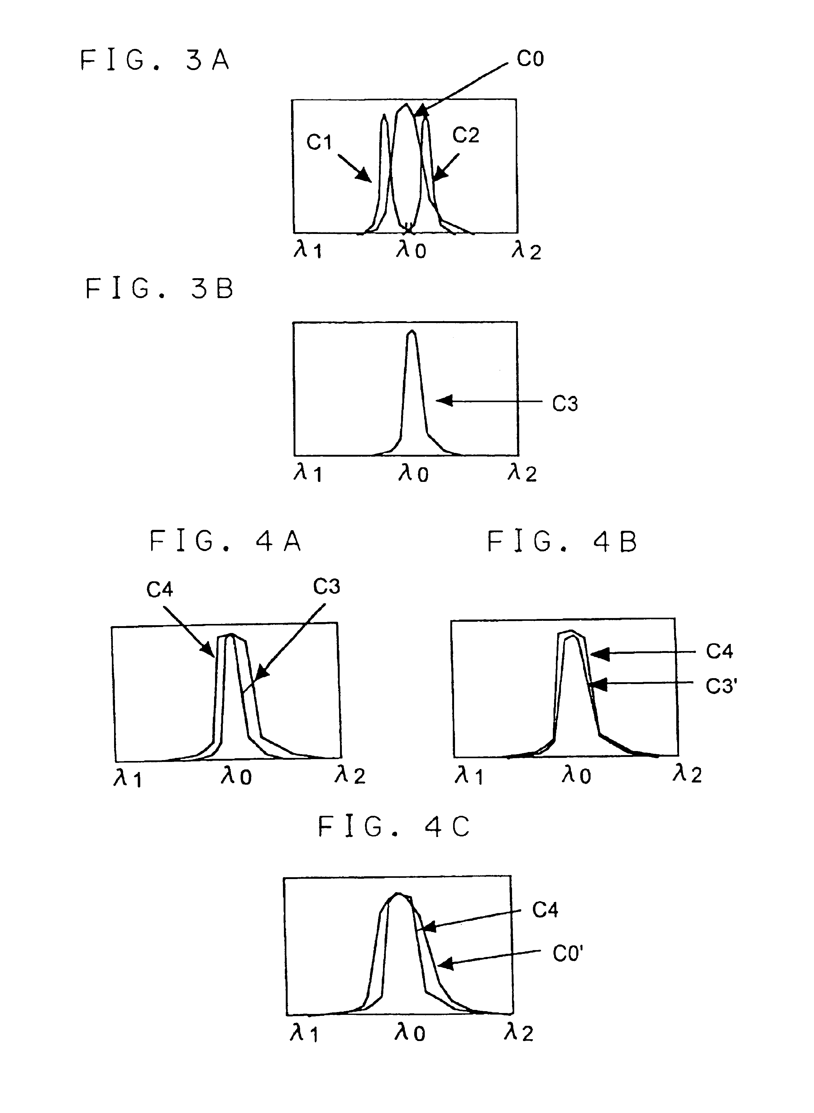
[0066]FIG. 13 shows the optical arrangement of a sixth embodiment of the invention. In this image display apparatus, the holographic magnifying optical element (5) has three diffraction center wavelengths respectively corresponding to three primary color components, i.e. R (red), G (green), and B (blue). The illumination light source is composed of three LEDs (1R, 1G, and 1B) and has three light mission center wavelengths, i.e. for R, G, and B, respectively corresponding to those diffraction center wavelengths. The holographic filter (4) has, for each of the R, G, and B wavelengths, two diffraction center wavelengths, i.e. a diffraction center wavelength shorter than the diffraction center wavelength of the holographic magnifying optical element (5) and a diffraction center wavelength longer than the diffraction center wavelength of the holographic magnifying optical element (5). Thus, the holographic magnifying optical element (5) restricts separately the three, i.e...


PUM


Abstract

An image display apparatus has an image display device for displaying an image, an eyepiece optical system, including a holographic magnifying optical element, for magnifying and projecting the image, and a holographic filter, disposed either as part of the image display device or in the optical path between the image display device and the eyepiece optical system, for restricting the wavelength range of the image light.

Description

[0001]This application is based on Japanese Patent Application No. 2001-80624 filed on Mar. 21, 2001, the contents of which are hereby incorporated by reference.BACKGROUND OF THE INVENTION[0002]1. Field of the Invention[0003]The present invention relates to an image display apparatus. More particularly, the present invention relates to, for example, an image display apparatus such as a HMD (head-mounted display) or HUD (head-up display) that operates by projecting a two-dimensional image formed on a liquid crystal display (LCD) onto an observer's eye on a see-through basis by using a holographic optical element (HOE).[0004]2. Description of the Prior Art[0005]Conventionally, various see-through-type image display apparatus have been proposed that present a projected image in a form superimposed on an image of the outside world by the use of a holographic optical element (U.S. Pat. No. 5,475,512, and Japanese Patent Applications Laid-Open Nos. 2001-4956, 2000-122589, H4-118620, and o...

Claims


Application Information

Patent Timeline
IPC IPC(8): G02B27/01G02B5/32G02B27/02H04N5/64
CPCG02B27/0172G02B2027/0178
Inventor ENDO, TAKESHIKOBAYASHI, YASUSHITANIJIRI, YASUSHINODA, TETSUYAUEDA, HIROAKI
Owner MINOLTA CO LTD
Why Eureka
Try Eureka