A creel device for an ultra-low liquor ratio yarn dyeing machine

A yarn dyeing machine and ultra-low bath technology, applied in the field of yarn dyeing machines, can solve the problems of low efficiency of dyeing and finishing equipment, long 3-4 hours, and high amount of dye auxiliaries, so as to enhance the dyeing and printing effect and reduce the cross-sectional area. , the effect of large contact area

Inactive Publication Date: 2011-12-28
高勋绿色智能装备(广州)有限公司
View PDF4 Cites 24 Cited by
  • Summary
  • Abstract
  • Description
  • Claims
  • Application Information

AI Technical Summary

Problems solved by technology

[0003] (1) The efficiency of dyeing and finishing equipment is low and the process time is long. The traditional overflow dyeing machine takes about 8-10 hours to dye a cylinder of cloth. The dyeing cycle is long, and the time-consuming is 3-3~ longer than that of foreign-made dyeing and finishing equipment. 4 hours
[0004] (2) The pollution is large, and each cylinder dyeing requires a large amount of dye auxiliaries
[0005] (3) The water consumption is large. The water consumption per kilogram of fabric of the traditional overflow dyeing machine is large, which is about 47% more than that of the foreign-made dyeing and finishing equipment.
[0006] (4) Power consumption is large. The power consumption of traditional overflow dyeing machine per thousand kilograms of fabric is about 380 kilowatt-hours, which is about 47% more than that of foreign dyeing and finishing equipment.
[0007] (5) Large bath ratio
Therefore, the required bath ratio is very low

Method used


Image

  • A creel device for an ultra-low liquor ratio yarn dyeing machine
  • A creel device for an ultra-low liquor ratio yarn dyeing machine
  • A creel device for an ultra-low liquor ratio yarn dyeing machine

Examples


Embodiment Construction

[0030] In order to deepen the understanding of the present invention, the present invention will be further described below in conjunction with the accompanying drawings and embodiments. It should be noted that the embodiments are only used to explain the present invention and do not constitute a limitation to the protection scope of the present invention.

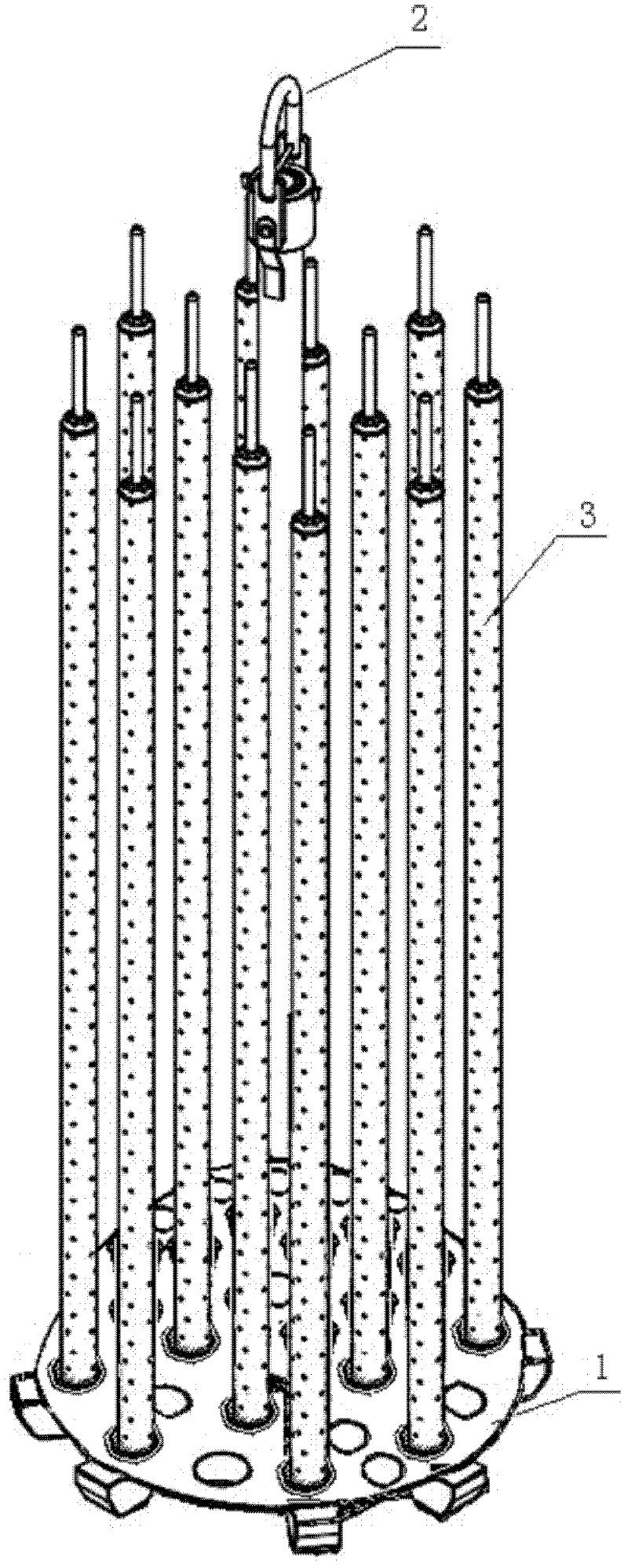
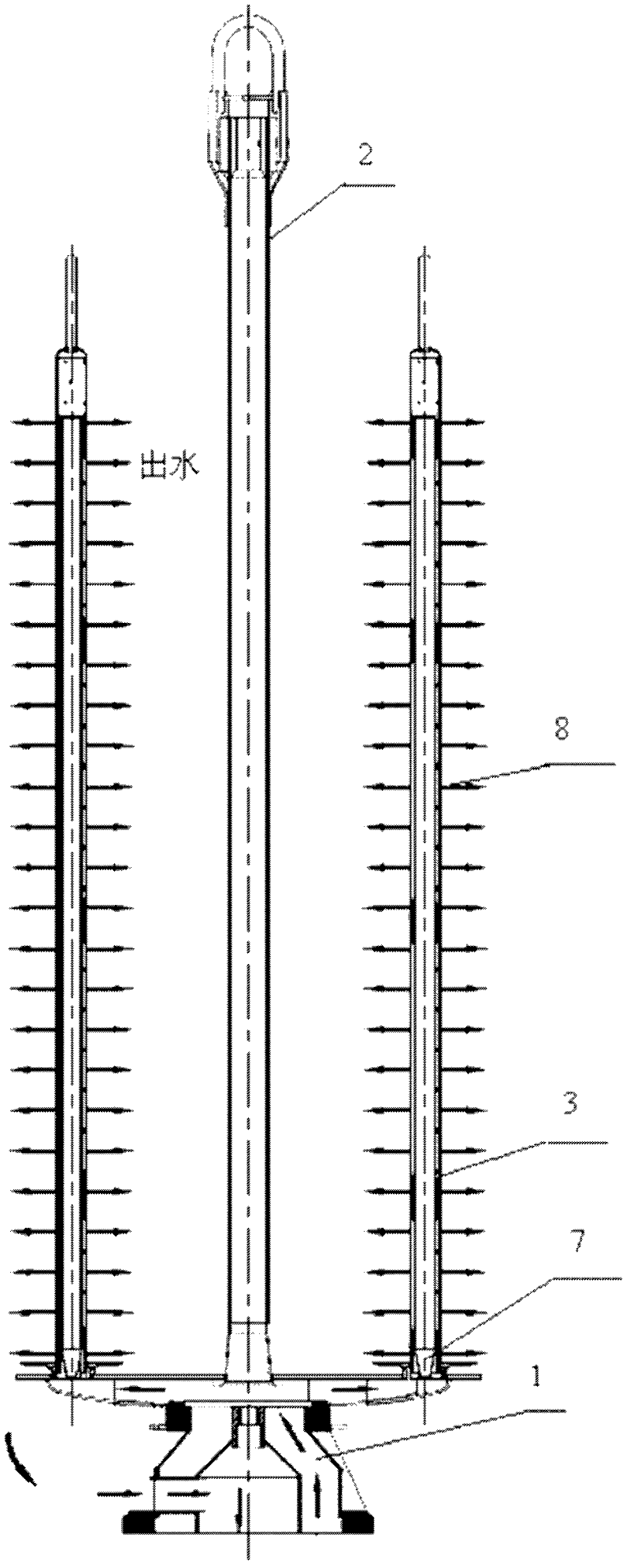
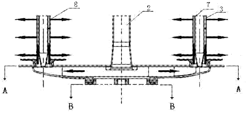
[0031] like Figure 1-4 As shown, a yarn creel device of an ultra-low liquor ratio yarn dyeing machine includes a sand table 1, a boom 2 and a yarn rod 3; The yarn rod 3 is a hollow cylinder structure, and a water drum 7 is arranged in the cylinder of the yarn rod 3. The water drum 7 is a hollow or solid columnar structure, and the yarn rod 3 and the water drum 7 are arranged on the same center line. The ratio of the hollow inner diameter of 3 to the outer diameter of water drum 7 is 10:7-9, and a plurality of water outlet holes 8 are uniformly arranged on the cylinder body of yarn rod 3 along the circumference of differen...


PUM


Abstract

The invention discloses a creel device of a yarn dyeing machine with an ultra-low bath ratio, which comprises a sand table, a suspender and a yarn rod, wherein the upper surface of the sand table is in a disk shape; the lower end of the sand table is in a cavity structure; the yarn rod is in a hollow barrel structure; a water drum is arranged in the barrel of the yarn rod and is in a hollow or solid columnar structure; the center line of the yarn rod and the center line of the water drum are same; the ratio of the hollow internal diameter of the yarn rod and the external diameter of the waterdrum is 10:7-9; and the barrel of the yarn rod is evenly provided with a plurality of water outlets along the circumference of horizontal cross sections of different heights. The hollow barrel of theyarn rod disclosed by the invention is provided with the water drum, which is favorable for reducing the volume of dye liquor in the yarn rod and for reducing a water bath ratio; under the same main pump power, the water drum is favorable for improving the practical lift of a pipeline relatively, the flow rate of the dye liquor in the yarn rod is improved, the levelling property of cheeses of upper layers and lower layers can be better guaranteed, and the one-time success rate for dyeing is improved; and from the bottom to the top, the water outlets on the barrel of the yarn rod at the outer side of the water drum are thicker at the higher place of the yarn rod, which is favorable for realizing the purpose of even dye transfer.

Description

technical field [0001] The invention relates to a yarn dyeing machine, in particular to a creel device of an ultra-low liquor ratio yarn dyeing machine, and the creel is arranged in a yarn vat of the yarn dyeing machine. Background technique [0002] Traditional package dyeing machines, also known as package dyeing machines, such as HTM series high temperature package dyeing machines, can be used for package dyeing of various chemical fibers and blended yarns, especially suitable for difficult-to-dye varieties such as cotton and tear cotton ; But there are following problems in this cheese dyeing machine: [0003] (1) The efficiency of dyeing and finishing equipment is low and the process time is long. The traditional overflow dyeing machine takes about 8-10 hours to dye a cylinder of cloth. The dyeing cycle is long, and the time-consuming is 3-3~ longer than that of foreign-made dyeing and finishing equipment. 4 hours. [0004] (2) The pollution is heavy, and the amount o...

Claims


Application Information

Patent Timeline
Patent Type & Authority Applications(China)
IPC IPC(8): D06B23/04D06B3/09
Inventor 黎嘉球钟汉如陈晓辉章红丽
Owner 高勋绿色智能装备(广州)有限公司
Why Eureka
Try Eureka