Connector module

Active Publication Date: 2016-11-15
WISTRON CORP
View PDF9 Cites 0 Cited by
  • Summary
  • Abstract
  • Description
  • Claims
  • Application Information

AI Technical Summary

Benefits of technology

The invention is a connector module that can protect its connecting part from damage and can easily be connected to an electronic device. The module has a protrusion component that sticks out of the device, acting as a protective barrier. When the module is not connected, the protrusion component or the device's outer casing prevents any damage to the connecting part. When the user wants to connect the module, the user only needs to move the connection interface towards the connecting part, and the connector will be pushed into the interface, making the connection easy and convenient.

Problems solved by technology

A connecting portion (e.g., a connection terminal) of the connector is generally designed to be exposed, and thus when the connector is not plugged, the connecting portion thereof is liable to deformation due to being subjected abrasion or damaged by an external force.
In addition, when the connecting portion is plugged into a corresponding connection interface, the connecting portion may also be deformed and damaged when subjecting to excessive insertion force due to tolerance in manufacturing and assembling.
The aforesaid conditions may both cause the connecting portion to result in poor electrical connection and become unable to perform power and signal transmissions normally.
Therefore, how to effectively protect the connecting portion of the connector without influencing its convenience in use is an important issue for those skilled in the field.

Method used


Image

  • Connector module
  • Connector module
  • Connector module

Examples


Embodiment Construction

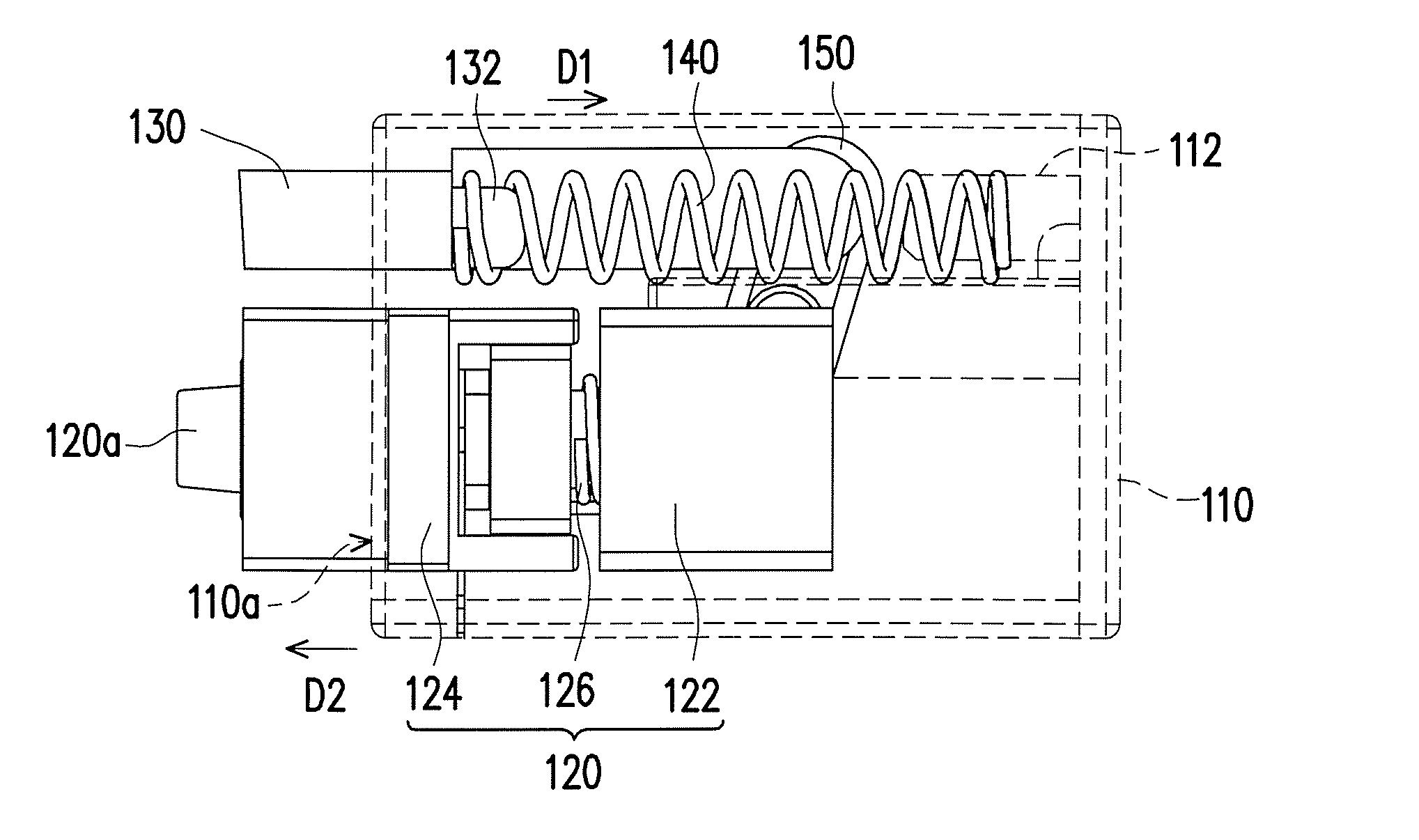
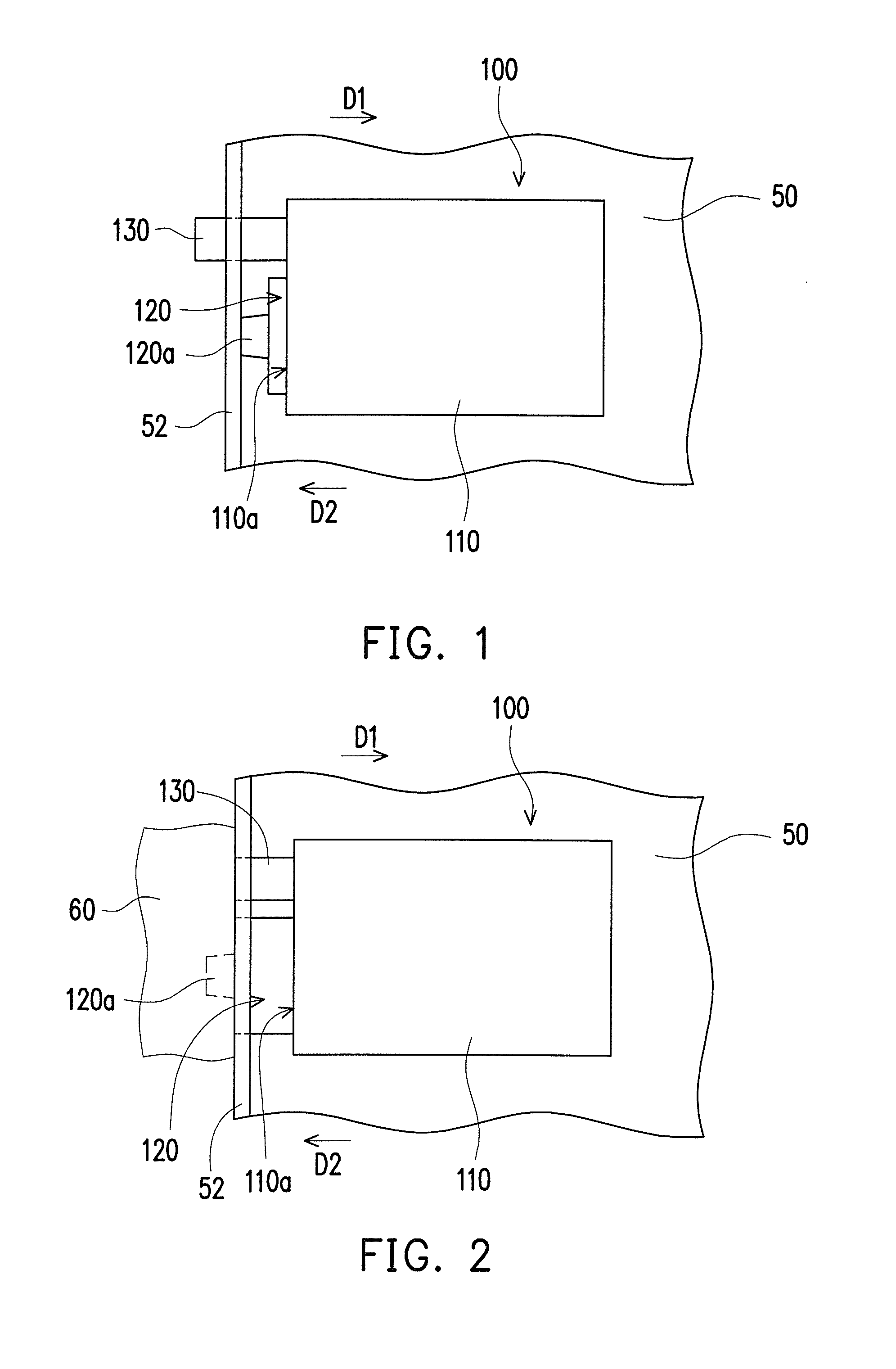
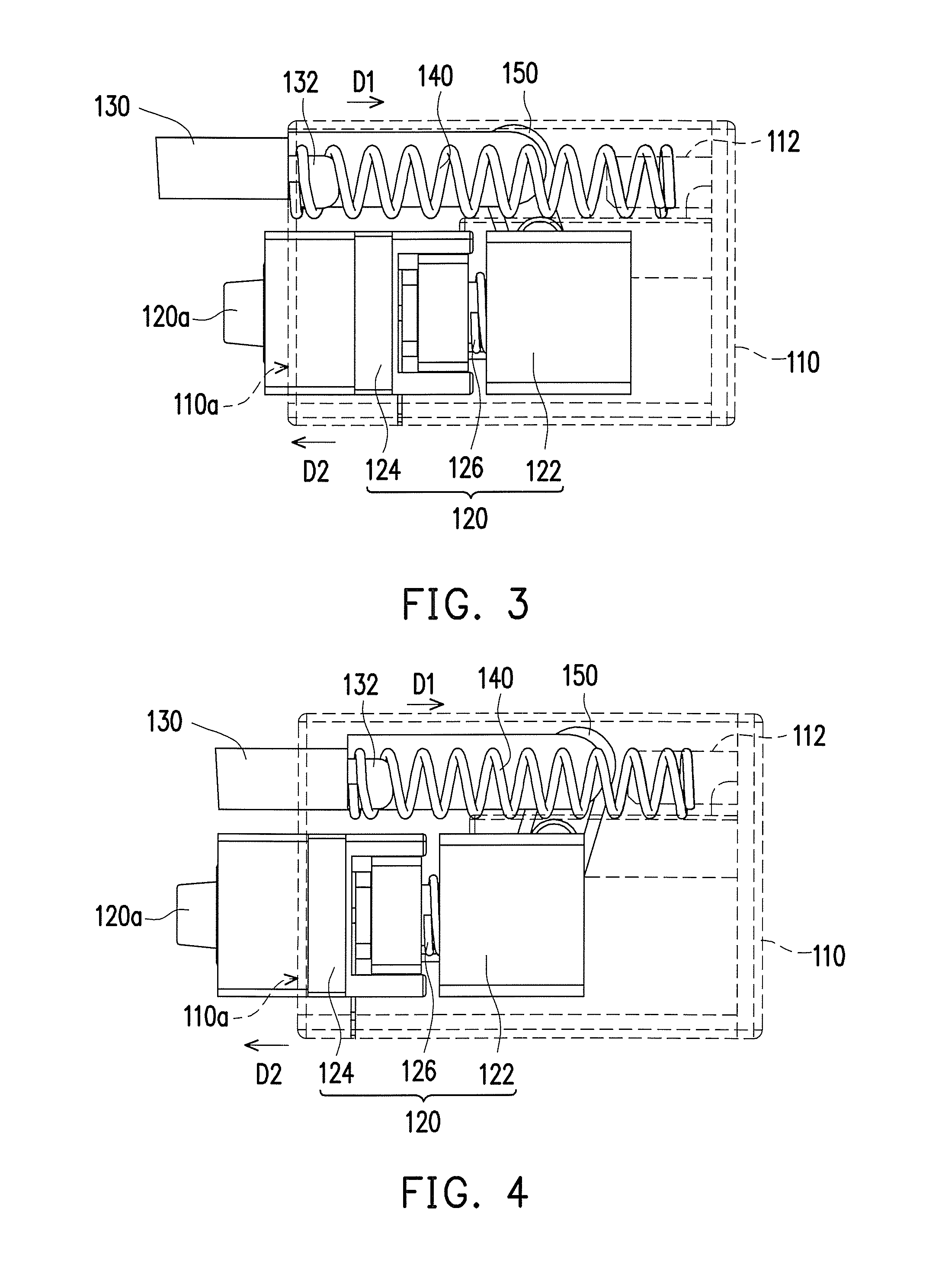
[0042]FIG. 1 illustrates a side view of a connector module 100 according to an embodiment of the invention. Referring to FIG. 1, the connector module 100 of the present embodiment is, for example, installed on an electronic device 50 and includes a main body 110, a connection component 120 and at least one protrusion component 130 (illustrated as one), wherein the connection component 120 and the protrusion component 130 are located at a same side of the main body 110. The main body 110 has an end surface 110a. The connection component 120 is disposed at the main body 110 and protrudes out of the end surface 110a of the main body 110. The connection component 120 is located within an outer casing 52 of the electronic device 50 and has a connecting portion 120a. The protrusion component 130 is disposed at the main body 110 and protrudes out of the end surface 110a, and the protrusion component 130 is protruded out of the outer casing 52 of the electronic device 50. In the present emb...


PUM


Abstract

A connector module adapted to be connected to a connection interface is provided. The connector module includes a main body, a connection component and at least one protrusion component. The connection component is disposed at the main body. The protrusion component is disposed at the main body. The protrusion component is adapted to receive an external force to move along a first direction, so as to change relative positions of the connection component and the protrusion component such that the connection component is adapted to be plugged into the connection interface along a second direction. The first direction is opposite to the second direction.

Description

CROSS-REFERENCE TO RELATED APPLICATION[0001]This application claims the priority benefit of Taiwan application serial no. 104123649, filed on Jul. 22, 2015. The entirety of the above-mentioned patent application is hereby incorporated by reference herein and made a part of this specification.BACKGROUND OF THE INVENTION[0002]1. Field of the Invention[0003]The invention generally relates to an electronic module, more particularly, to a connector module.[0004]2. Description of Related Art[0005]With the development of electronic technology, connectors are broadly applied in various electronic devices and their corresponding connecting lines, such as notebook computers, Tablet PCs, Smart Phones and their transmission lines. By plug connecting two connectors with each other, signals may be transmitted between the electronic devices.[0006]A connecting portion (e.g., a connection terminal) of the connector is generally designed to be exposed, and thus when the connector is not plugged, the ...

Claims


Application Information

Patent Timeline
IPC IPC(8): H01R13/62H01R13/642H01R13/635
CPCH01R13/642H01R13/635
Inventor LAN, CHANG-FENG
Owner WISTRON CORP
Why Eureka
Try Eureka