Thermocouple structure

a technology of thermocouple and support structure, which is applied in the direction of instruments, heat measurement, measurement devices, etc., can solve the problems of premature defects and failures, and achieve the effect of preventing the destruction of mechanical structures

Pending Publication Date: 2021-12-16
WLKA ALEXANDER WIEGAND SE & CO KG +1
View PDF5 Cites 0 Cited by
  • Summary
  • Abstract
  • Description
  • Claims
  • Application Information

AI Technical Summary

Benefits of technology

[0006]It is therefore an object of the present invention to provide a thermocouple sensing structure for measurement of a temperature distribution inside of a vessel filled fully or partially with catalyst particles, or of a temperature distribution inside of a vessel filled with a liquid phase or a multiphase mixed process medium, such as a hydrocracking reaction stream with catalyst particles or droplets, and hydrogen and solid impurities, thereby preventing the destruction of the mechanical structure of the thermocouple caused by the flow and turbulence of the process medium and the abrasion damage of the surface of the thermocouple outer sheath by the multiphase fluid. The present invention, namely the support for flexible thermocouple can be used for all of the fluidized bed hydrocracking process, such as Eni EST, KBR VCC, etc. The present invention is a good solution for temperature measurement of fluidization reaction system.

Problems solved by technology

However, as the multiphase substance consisting of the reactant, reaction product, catalyst and so on flow continually upwards from the inlet to the outlet, the thermocouple is suffering from the uneven tensile stress, torsional stress and so on caused by the hydraulic resistance, then there is an abrasion on the surface of the thermocouple caused by the flowing material, leading to premature defects and failures.

Method used


Image

  • Thermocouple structure
  • Thermocouple structure
  • Thermocouple structure

Examples


Embodiment Construction

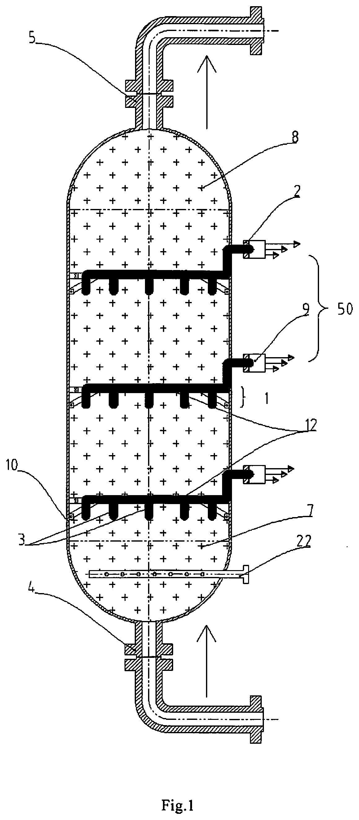
[0033]FIG. 1 shows a vessel 10 having a support structure 1 for a thermocouple element (hereinafter referred to as TC element). Up to 9 or more (levels of) support structures could be applied in a vessel. Each support structure has one or more thermocouple elements (equivalent to the thermocouple sensing elements) for measuring the temperatures on different locations within the vessel filled fully or partially with catalyst particles, or multi-phase process flow consisting of residue oil, hydrocarbon, hydrogen, cracked oil / gas products, sulfur, and catalyst particles or droplets. According to the embodiment, up to 5 to 15 TC elements are provided, preferably 12 TC elements are supported at 7 to 12 levels of support structure, preferably at 9 levels of support structure

[0034]The vessel has different openings 4, 5 and 22 for the introduction of various materials, and is full of a mixture consisting of liquid hydrocarbon, gaseous hydrocarbon, catalyst particles / liquid drops 8, hydrogen...


PUM

PropertyMeasurementUnit
outer diameteraaaaaaaaaa
diameteraaaaaaaaaa
temperatureaaaaaaaaaa

Abstract

A thermocouple sensing structure for measurement of a temperature distribution inside of a vessel (10) filled fully or partially with multi-phase fluid consisting of residue oil, hydrogen, cracked oil/gas products, sulfur, catalyst particles or catalyst droplets, etc., the thermocouple sensing structure consists of a support structure (1) and a number of thermocouple sensing elements (3), the thermocouple sensing elements (3) are partially or fully covered by the support structure (1), and wherein the closed tip (3B,3C,3D,3M) of the thermocouple sensing element (3) is passed through the support structure (1) to the inside of the vessel (10). And a support structure (1) for fixation of a thermocouple sensing element (3) in a vessel (10), in particular suitable for use in thermocouple sensing structure, the support structure (1) has a protection portion for protection of at least a lower portion of at least one thermocouple sensing element (3) relative to an upward flow direction of a fluid in the vessel (10). The static pressure of the fluid in the vessel (10) is beard by a sheath of the thermocouple such that a requirement for the strength and shape of the support structure (1) is significantly decreased. Therefore, the effect on the fluid flow field in the vessel (10) and the fluid hydraulic resistance of the temperature measurement system are reduced to a minimum level.

Description

FIELD OF THE INVENTION[0001]The invention relates to a thermocouple sensing element and support structure for fixation of the thermocouple sensing element in a vessel, in particularly, relates to a support structure for flexible thermocouples inside of a slurry material or multiphase fluid vessel, for example a reactor full of multiphase mixture consisting of liquid hydrocarbon, gaseous hydrocarbon, catalyst particles / liquid drop, hydrogen and Sulphur etc. Hydraulic protection is provided to the thermocouples (TC) with an outer diameter of 3-30 mm, typically with an out diameter of ¼′, 5 / 16′, ⅜′ or ½′, and thereby impacts possibly generated by the support structure on the fluid field of the multiphase mixture inside of the vessel can be avoided.BACKGROUND OF THE INVENTION[0002]Slurry material vessels are known in the prior art. For example, U.S. Pat. No. 9,937,476 illustrates a slurry material vessel.[0003]Raw oil and catalyst are introduced from a lower end of the vessel in these s...

Claims


Application Information

Patent Timeline
Patent Type & Authority Applications(United States)
IPC IPC(8): G01K7/02G01K1/024G01K1/14G01K1/08
CPCG01K7/02G01K1/14G01K1/024
Inventor LIU, YUNBOTIER, MICHAELCOOTS, SCOTTTORGERSON, ROBERTPOTEET, ROBERT FRANCISZHANG, SONG
Owner WLKA ALEXANDER WIEGAND SE & CO KG
Why Eureka
Try Eureka