
Balun device for UHF signals

a balun device and ultra high frequency technology, applied in the field of rf signals, can solve the problems of high fabrication cost, inability to adapt to terrestrial digital television signals in the uhf band, and conventional baluns with relatively narrow bandwidth

Active Publication Date: 2016-11-29
TRANS ELECTRIC
View PDF3 Cites 0 Cited by
  • Summary
  • Abstract
  • Description
  • Claims
  • Application Information

AI Technical Summary

Benefits of technology

The invention relates to a balun device for UHF signals that solves problems in previous designs. The balun device includes a base plate, two connection pads, a conductive track, and a conductive ground pattern. The connection pads connect to differential signal lines and a single-ended signal line, while the conductive track connects them. The ground pattern surrounds the conductive track and pads, providing better signal quality and minimizing interference. It is designed to improve the performance of balun devices used in high-frequency applications such as UHF signals.

Problems solved by technology

However, such conventional RF balun requires expensive fabrication materials, and involves a process for soldering the magnetic core onto a printed circuit board (PCB), thereby resulting in a high fabrication cost.
Thus, this conventional balun with relatively narrow bandwidth is not suitable for terrestrial digital television signals in the UHF band.

Method used


Image

  • Balun device for UHF signals
  • Balun device for UHF signals
  • Balun device for UHF signals

Examples


Embodiment Construction

[0016]Before the disclosure is described in greater detail, it should be noted herein that like elements are denoted by the same reference numerals throughout the disclosure.

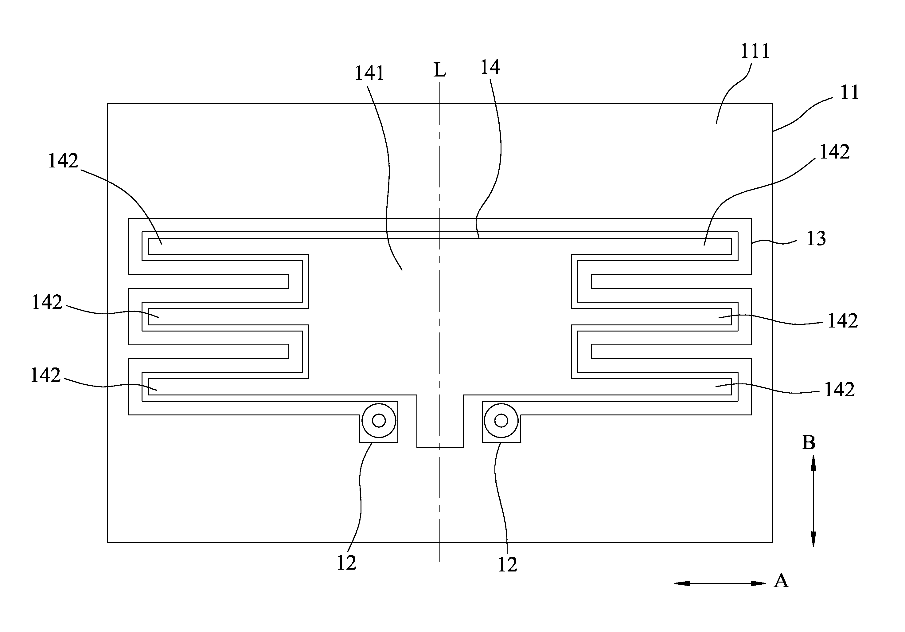
[0017]Referring to FIG. 3, the embodiment of a balun device according to this disclosure is shown to be used to match between a single-ended (or unbalanced) signal and a pair of differential (or balanced) signals in, for example, an ultra high frequency (UHF) range. The balun device includes a dielectric base plate 11, two conductive connection pads 12, a printed conductive track 13, and a conductive ground pattern 14. In this embodiment, the conductive connection pads 12, the printed conductive track 13 and the conductive ground pattern 14 are coplanarly formed on the dielectric base plate 11.

[0018]In this embodiment, the dielectric base plate 11 is in the form of a rectangular printed circuit board, and is made of, for example, Bakelite or fiberglass.

[0019]The conductive connection pads 12 are formed on a base...


PUM


Abstract

A balun device for UHF signals includes two conductive connection pads, a printed conductive track and a conductive ground pattern that are formed on a dielectric base plate. The conductive connection pads are connectable respectively with a pair of first signal lines for a pair of differential signals. One of the conductive connection pads is further connectable with a second signal line for a single-ended signal. The printed conductive track interconnects electrically the conductive connection pads. The conductive ground pattern is surrounded by and spaced apart from the printed conductive track and the conductive connection pads.

Description

CROSS-REFERENCE TO RELATED APPLICATION[0001]This application claims priority to Taiwanese Application No. 104201223, filed on Jan. 26, 2015, the contents of which are hereby incorporated by reference.FIELD[0002]The disclosure relates to a converter for radio frequency (RF) signals, and more particularly to a balun device for ultra high frequency (UHF) signals.BACKGROUND[0003]A balun is used to match between a single-ended (or unbalanced) signal and a pair of differential (or balanced) signals.[0004]Typically, a conventional RF balun is in the form of a magnetic core wound with windings. Such RF balun has a wide working frequency band of up to a GHz-level. Referring to FIG. 1, a curve 91 illustrates partially an insertion loss measurement result of such conventional RF balun within a frequency range of from 450 MHz to 790 MHz. From the curve 91 of FIG. 1, such conventional RF balun has an insertion loss less than −6 dB such that it is suitable for RF signals within an UHF band of fro...

Claims


Application Information

Patent Timeline
IPC IPC(8): H01P5/10H03H7/42H01P3/08
CPCH01P5/10
Inventor LIN, PAUL
Owner TRANS ELECTRIC
Features
  • Generate Ideas
  • Intellectual Property
  • Life Sciences
  • Materials
  • Tech Scout
  • Unparalleled Data Quality
  • Higher Quality Content
  • 60% Fewer Hallucinations
Learn More