
Systems and methods for treatment of sleep apnea

a technology for sleep apnea and sleep disorder, applied in the field of systems and methods for treating sleep apnea, can solve the problems of unobstructed airway, and obstructive collapse, and reducing the frequency of apneic events. , the effect of reducing the tendency to collapse during sleep

Inactive Publication Date: 2016-12-06
REVENT MEDICAL
View PDF191 Cites 0 Cited by
  • Summary
  • Abstract
  • Description
  • Claims
  • Application Information

AI Technical Summary

Benefits of technology

The invention relates to a method and devices to treat sleep apnea. The method involves implanting a device in the airway-forming tissue to change its shape and remodel it, making the airway unobstructed during sleep and reducing apneic events. The device is designed to accommodate bioerodible material, which is used to stabilize the implant shape after placement. The method includes shaping the device to match the airway shape and size, and remodeling it to conform to the airway site in a way that preserves its physiological function. This results in an unobstructed airway and reduced apneic events.

Problems solved by technology

In typical embodiments of the method, remodeling the airway-forming tissue results in the airway being unobstructed during sleep, and further, typically, the thus-unobstructed airway diminishes the frequency of apneic events.

Method used


Image

  • Systems and methods for treatment of sleep apnea
  • Systems and methods for treatment of sleep apnea
  • Systems and methods for treatment of sleep apnea

Examples


Embodiment Construction

A. Anatomy of the Pharynx

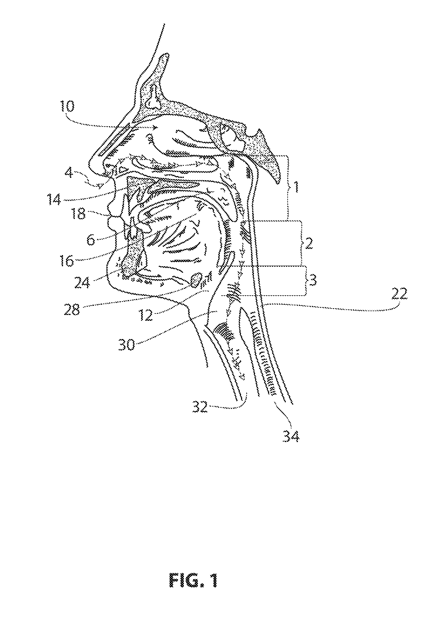
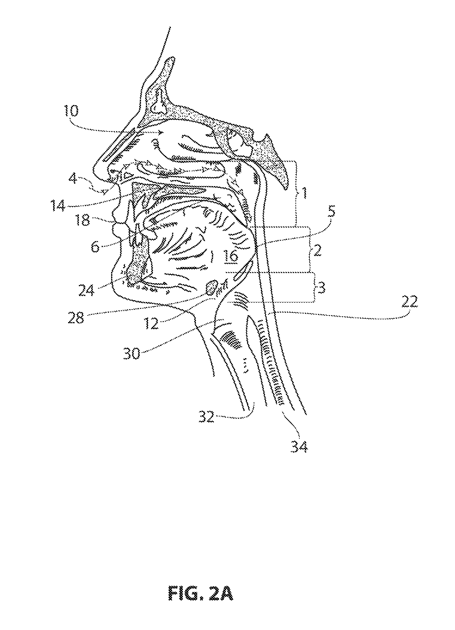
[0094]FIG. 1 is a sagittal view of the structures that form the pharyngeal airway 4; some of these structures can become compromised under various conditions to the extent that they obstruct or occlude passage of air through the airway 4, and thus contribute to obstructive sleep apnea. The pharynx is divided, from superior to inferior, into the nasopharynx 1, the oropharynx 2 and the hypopharynx 3. Variations of FIG. 1 are provided in FIGS. 2A and 2B which depict airway obstruction sites 5 at various levels in the pharyngeal airway. FIG. 2A, for example, shows an occlusion 5 at the level of the oropharynx 2, where the base of the tongue 16 and a thickened posterior pharyngeal wall 22 have collapsed against each other. FIG. 2B provides a view of a compromised airway with palate closure. It is also possible for airway obstruction to occur at the level of the nasopharynx 1, where an elongated and / or floppy soft palate can collapse against a thickened posterior ...


PUM

PropertyMeasurementUnit
widthaaaaaaaaaa
threshold displacementaaaaaaaaaa

Abstract

An implant for treating an obstructive airway disorder includes an elongate implant body configured for implanting in airway-interface tissue. At least a portion of the elongate body carries a light transmission material for permitting light transmission therein. Systems and methods of treating an airway disorder including implanting an implant in an airway-interface tissue are also provided.

Description

CROSS-REFERENCE TO RELATED APPLICATIONS[0001]This application claims priority to: U.S. Provisional Application No. 61 / 347,348 filed May 21, 2010; U.S. Provisional Application No. 61 / 347,356 filed May 21, 2010; U.S. Provisional Application No. 61 / 367,707 filed Jul. 26, 2010; U.S. Provisional Application No. 61 / 418,238 filed Nov. 30, 2010; U.S. Provisional Application No. 61 / 419,690 filed Dec. 3, 2010.INCORPORATION BY REFERENCE[0002]This application is related to co-pending patent applications: U.S. application Ser. No. 11 / 969,201 filed Jan. 3, 2008; U.S. application Ser. No. 12 / 937,564 filed Jan. 3, 2011; U.S. application Ser. No. 13 / 053,025 filed Mar. 21, 2011; U.S. application Ser. No. 13 / 053,059 filed Mar. 21, 2011. All publications, patents and patent applications mentioned in this specification are herein incorporated by reference to the same extent as if each individual publication, patent or patent application was specifically and individually indicated to be incorporated by r...

Claims


Application Information

Patent Timeline
Patent Type & Authority Patents(United States)
IPC IPC(8): A61F2/00A61F5/56
CPCA61F2/00A61F5/566A61F2210/0004
Inventor GILLIS, EDWARD M.SHADDUCK, JOHN H.TRUCKAI, CSABAPOUTIATINE, ANDREWBUSCEMI, PAUL J.
Owner REVENT MEDICAL
Learn More