
Systems and methods for treatment of sleep apnea

a technology for sleep apnea and sleep disorder, applied in the field of systems and methods for treating sleep apnea, can solve the problems of unobstructed airway, and obstructive collapse, and reducing the frequency of apneic events. , the effect of reducing the tendency to collapse during sleep

Inactive Publication Date: 2011-09-22
REVENT MEDICAL
View PDF101 Cites 21 Cited by
  • Summary
  • Abstract
  • Description
  • Claims
  • Application Information

AI Technical Summary

Benefits of technology

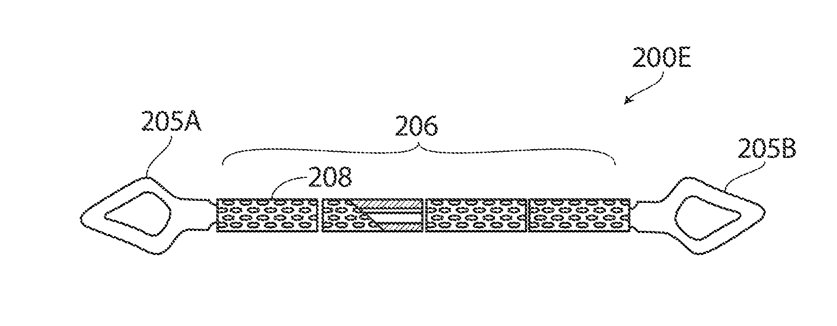
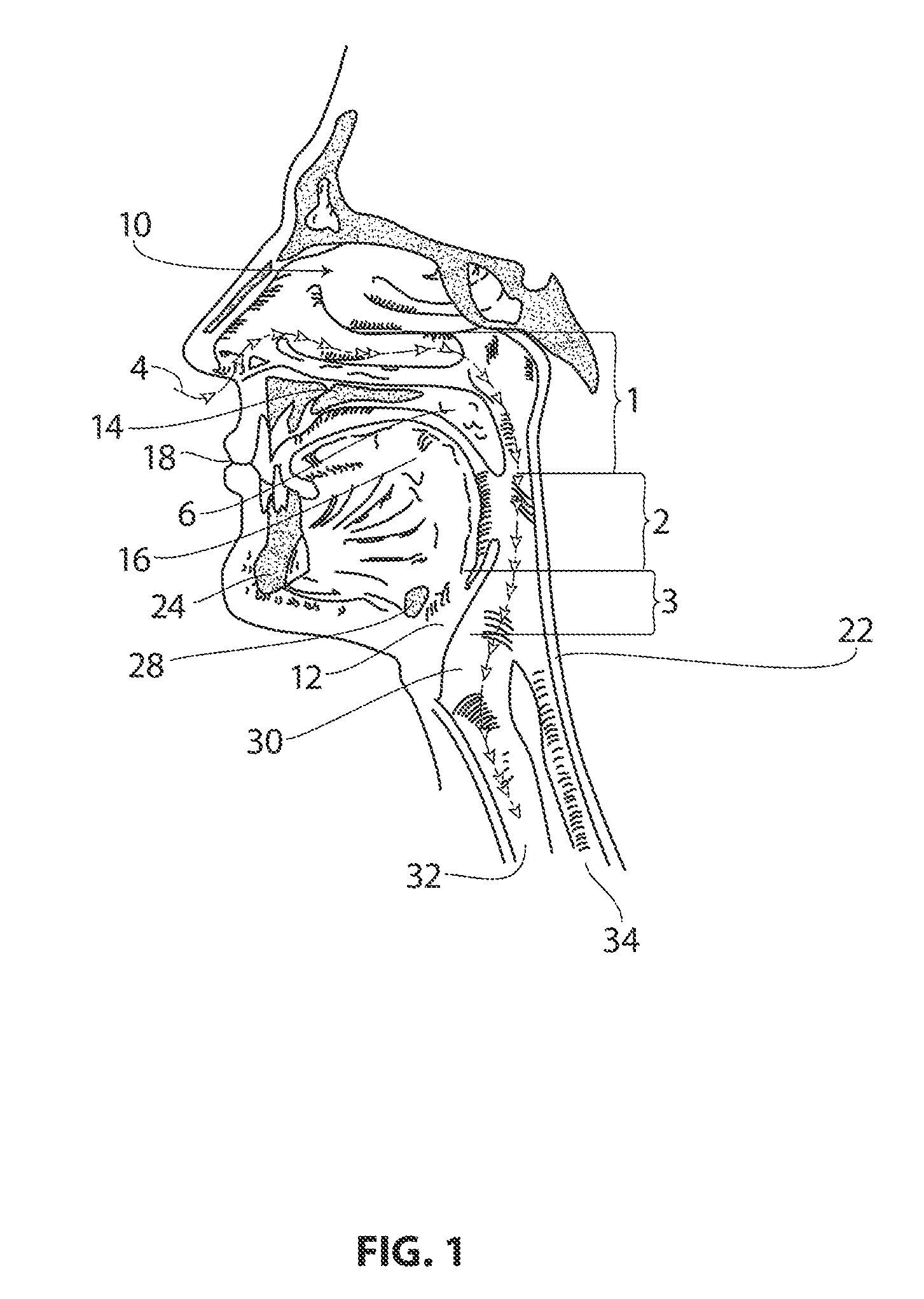
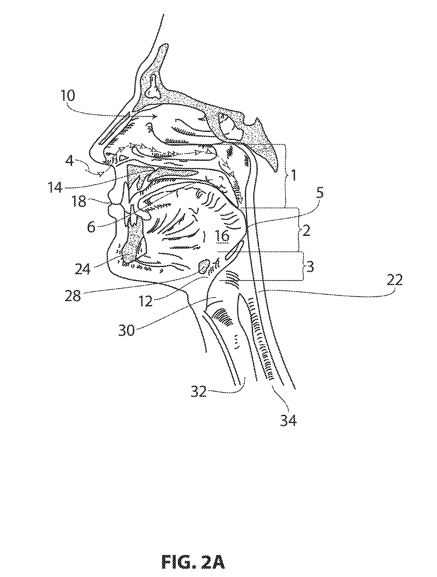
[0007]The invention relates to a method of alleviating obstructive collapse of airway-forming tissues, and for devices with which to implement the method. Typical patients for whom the method and device may provide therapeutic benefit are those who suffer from obstructive sleep apnea. The method includes implanting a device at a site in the tissue and bioeroding the bioerodible portion of the device to change the shape of the device and to remodel the airway-forming tissue. The implanted device is sized and shaped to conform to the airway-forming tissue site in a manner compatible with normal physiological function of the site; and includes a resiliently deformable portion and a bioerodible portion. In typical embodiments of the method, remodeling the airway-forming tissue results in the airway being unobstructed during sleep, and further, typically, the thus-unobstructed airway diminishes the frequency of apneic events. Remodeling may include reshaping or otherwise altering the position or conformation of airway associated tissue so that its tendency to collapse during sleep is diminished.
[0012]In another aspect of the methods described herein, a method of forming a device to alleviate obstructive collapse of an airway during sleep is provided. The method includes forming a resiliently deformable material into an initial shape that corresponds to the preferred shape of the device, the initial shape having a site for accommodating bioerodible material; changing the initial shape of the resiliently deformable material into a non-preferred shape that is sized and configured into an implantable shape that conforms to an airway-forming tissue site and is compatible with normal physiological function after implantation; and stabilizing the implantable shape by incorporating the bioerodible material into the accommodating site. In some of these method embodiments, changing the initial shape of the resiliently deformable material includes absorbing a force sufficient to remodel the airway as the force is transferred from the device into an implant site after implantation of the device. That level of force is further typically insufficient to remodel the airway to an extent that it is unable to move in a manner that allows substantially normal or acceptable physiological function of the airway.

Problems solved by technology

In typical embodiments of the method, remodeling the airway-forming tissue results in the airway being unobstructed during sleep, and further, typically, the thus-unobstructed airway diminishes the frequency of apneic events.

Method used


Image

  • Systems and methods for treatment of sleep apnea
  • Systems and methods for treatment of sleep apnea
  • Systems and methods for treatment of sleep apnea

Examples


embodiment 770

[0098]FIG. 26 depicts an alternative embodiment 770 of in-situ adjustable implant body having an elastomeric medial region 772 for applying forces to tissue. The medial region 722 again includes at least one interior chamber 775 filled with a fluid, for example a biocompatible fluid such as saline 720, that is filled under pressure with the implant body in a stretched condition. In this embodiment, the chamber 775 comprises a non-linear lumen, such as a helical lumen, that can be filled with an incompressible fluid or the fluid can be released from the lumen. It can be understood that if the helical lumen is fluid-filled, the elastomeric material can still apply retraction forces after being disposed in a treatment site, but the fluid 720 will lessen or dampen the applied forces provided by the implant. If the fluid 720 is evacuated from the lumen 775, then the elastomeric portion will apply retraction forces without being impinged by the fluid. FIG. 26 depicts a needle tip 730 punc...

embodiment 780

[0100]FIG. 28 depicts another similar embodiment 780 wherein the implant carries a plurality of non-linear lumens 782A and 782B that each are filled with an incompressible fluid 720 that can be released independently through a seal 785A or 785B such as by any means described above to adjust the retraction forces applied by the implant. In the implant of FIG. 28, two helically-configured lumens 782A and 782B that overlap are shown, but the plurality of lumens can range from 2 to 10 or more and comprise axially overlapping lumens, partly overlapping lumens or non-overlapping lumens.

[0101]FIG. 29 depicts an implant embodiment 790 similar to that of FIG. 28 wherein the implant 790 again carries a plurality of lumens 792A-792C that are both non-linear (helical) and lineareach within elastomeric, axial-extending regions 795A-795C, respectively. In this embodiment, it can be understood that each linear lumen 792B, 792C is filled with an incompressible fluid 720 that maintains the associate...

embodiment 800

[0102]FIG. 30 depicts an alternative embodiment 800 that is similar to those described above except a permeable wall 802 surrounding the fluid-filled interior chamber 805 can be slightly permeable to allow a controlled migration of fluid 720 from the chamber to thus allow the elastomeric material to apply greater retraction forces to the tissue. The interior chamber or chambers can be non-linear or linear to thus function as described previously to permit the implant to increase retraction forces applied by implant to the treatment site.

[0103]In another embodiment, an implant similar to that of FIG. 30 can have an interior chamber filled with a salt and moisture absorbed through the slightly permeable wall can cause the salt to dissolve which will change the forces applied by the implant, typically to reduce the forces applied by the implant.


PUM

PropertyMeasurementUnit
thicknessesaaaaaaaaaa
timeaaaaaaaaaa
wetting contact angleaaaaaaaaaa

Abstract

A system for treating an airway disorder is provided with an implant body configured to conform to an airway-interface tissue site in a manner compatible with normal physiological function of the site. In some embodiments, the implant body includes an adjustment element configured to allow in-situ adjustment of the implant body between first and second tensioning forces applied to the site. Methods of using such systems are also provided.

Description

CROSS-REFERENCE TO RELATED APPLICATIONS[0001]This application claims priority to: U.S. Provisional Application No. 61 / 315,835 filed Mar. 19, 2010; U.S. Provisional Application No. 61 / 315,838 filed Mar. 19, 2010; U.S. Provisional Application No. 61 / 347,348 filed May 21, 2010; U.S. Provisional Application No. 61 / 347,356 filed May 21, 2010; U.S. Provisional Application No. 61 / 367,707 filed Jul. 26, 2010; U.S. Provisional Application No. 61 / 418,238 filed Nov. 30, 2010; U.S. Provisional Application No. 61 / 419,690 filed Dec. 3, 2010.INCORPORATION BY REFERENCE[0002]All publications, patents and patent applications mentioned in this specification are herein incorporated by reference to the same extent as if each individual publication, patent or patent application was specifically and individually indicated to be incorporated by reference.FIELD OF THE INVENTION[0003]The invention relates to the field of methods and devices for the treatment of obstructive sleep apnea, and more particularly ...

Claims


Application Information

Patent Timeline
Patent Type & Authority Applications(United States)
IPC IPC(8): A61F5/56
CPCA61F2/00A61F5/566A61F2210/0004A61F5/56
Inventor GILLIS, EDWARD M.POUTIATINE, ANDREWSHADDUCK, JOHN H.TRUCKAI, CSABA
Owner REVENT MEDICAL
Learn More