
Systems and methods for treatment of sleep apnea

a technology for sleep apnea and sleep apnea, which is applied in the field of methods and devices for the treatment of obstructive sleep apnea, can solve the problems of reducing unobstructed airway, and obstructive collapse, so as to reduce the tendency to collapse during sleep, reduce the frequency of apneic events, and prevent obstructive collaps

Inactive Publication Date: 2017-08-03
GILLIS EDWARD M +5
View PDF1 Cites 2 Cited by
  • Summary
  • Abstract
  • Description
  • Claims
  • Application Information

AI Technical Summary

Benefits of technology

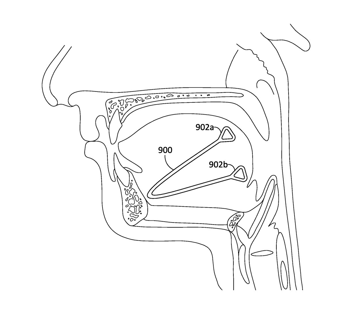
The invention describes a method and devices for treating sleep apnea by implanting a device in the airway tissue to change its shape and remodel the tissue to prevent apneic events during sleep. The device is made of a resiliently deformable material that is shaped and conformed to the airway tissue, and a bioerodible material that is used to stabilize the device's shape. The method involves altering the shape of the device to conform to the airway tissue and remodel it, resulting in an unobstructed airway during sleep and reducing apneic events.

Problems solved by technology

In typical embodiments of the method, remodeling the airway-forming tissue results in the airway being unobstructed during sleep, and further, typically, the thus-unobstructed airway diminishes the frequency of apneic events.

Method used


Image

  • Systems and methods for treatment of sleep apnea
  • Systems and methods for treatment of sleep apnea
  • Systems and methods for treatment of sleep apnea

Examples


example 1

ontraction Accelerated Testing

[0405]An in vitro test system was developed to demonstrate the fatigue behavior of the restricting coils and simulate the expected motion after implantation. While not wishing to be limited to any theory, it is thought that the characteristic motions of the coiled implant when implanted are initially multiplanar bending. While some stretching of the device may occur, contraction is substantially prevented until the supporting coils degrade.

[0406]In order to evaluate the relative performance of types of coils, sets of implants with different durometer silicone cores and with coils that were either fused or open-ended within segments were rested. Coils with diameters of 0.009″ or 0.013″ were tested in 0.1M saline at 37° C. in a 20 L bath. The coils were made to oscillate by fixing one end and placing the body of the implant in a moving stream such that bending occurred at an approximate frequency of 2 Hz with a randomly oriented 15 degree to 30 degree ben...

example 2

[0409]The effect of fusing implant coils together to prevent the coils from prematurely unwinding on the implant contraction rate was further tested using a canine animal model. Comparable implant systems having resilient, long term implants initially held in expanded shapes by coiled bioerodable implant material with (FIGS. 118 C-D) and without (FIGS. 118 A-B) fused coils were placed on both left and right sides of animals' tongues and soft palates and the bioerodable material bioeroded to allow the resilient, long term implants to foreshorten. The implant lengths were measured as a function of length of time since implantation. Noting that the time scales are different, as seen by the more gradually downward sloping curves going from the initial implant lengths (at time=0) to the equilibrium (foreshortened) implant lengths in the results shown with the fused coils placed in the right and left sides of the tongue (“Right tongue” and “Left tongue”, respectively) as shown FIGS. 118 C...


PUM


Abstract

A method of maintaining airway patency in an airway of a patient. The method includes the steps of implanting a device into airway-forming tissue without affixing the device to the tissue and permitting a bioerodable portion of the device to bioerode to apply a force to the airway-forming tissue to maintain airway patency. The invention also provides devices for practicing the method.

Description

CROSS REFERENCE TO RELATED APPLICATIONS[0001]The present application claims priority as a continuation-in-part of U.S. application Ser. No. 14 / 674,986, filed Mar. 31, 2015; which is a continuation of U.S. application Ser. No. 13 / 711,537, filed Dec. 11, 2012, now U.S. Pat. No. 8,991,398; which is a continuation of U.S. application Ser. No. 13 / 269,520, filed Oct. 7, 2011, now U.S. Pat. No. 8,327,854; which is a continuation of U.S. application Ser. No. 12 / 937,564, filed Jan. 3, 2011, now U.S. Pat. No. 8,707,960; which is a 371 of International Application No. PCT / US2009 / 043450, filed May 11, 2009; which claims the benefit of U.S. Provisional Patent Application No. 61 / 052,586, filed May 12, 2008.[0002]The present application also claims priority as a continuation-in-part of U.S. application Ser. No. 15 / 198,826, filed Jun. 30, 2016; which is a continuation of U.S. application Ser. No. 14 / 289,475, filed May 28, 2014, now U.S. Pat. No. 9,381,109; which is a divisional of U.S. application ...

Claims


Application Information

Patent Timeline
Patent Type & Authority Applications(United States)
IPC IPC(8): A61F5/56
CPCA61F5/566
Inventor GILLIS, EDWARD M.SHADDUCK, JOHN H.TRUCKAI, CSABAPOUTIATINE, ANDREWBUSCEMI, PAUL J.IANCEA, OCTAVIAN
Owner GILLIS EDWARD M
Learn More