
Method and apparatus for operator supervision and direction of highly autonomous vehicles

a highly autonomous, operator-supervised technology, applied in the direction of vehicle position/course/altitude control, process and machine control, instruments, etc., can solve the problems of complex and variable identification, current methods for establishing the future path of vehicle movement are either too limited, too time-consuming,

Active Publication Date: 2016-12-27
THE UNITED STATES OF AMERICA AS REPRESETNED BY THE SEC OF THE AIR FORCE
View PDF7 Cites 8 Cited by
  • Summary
  • Abstract
  • Description
  • Claims
  • Application Information

AI Technical Summary

Benefits of technology

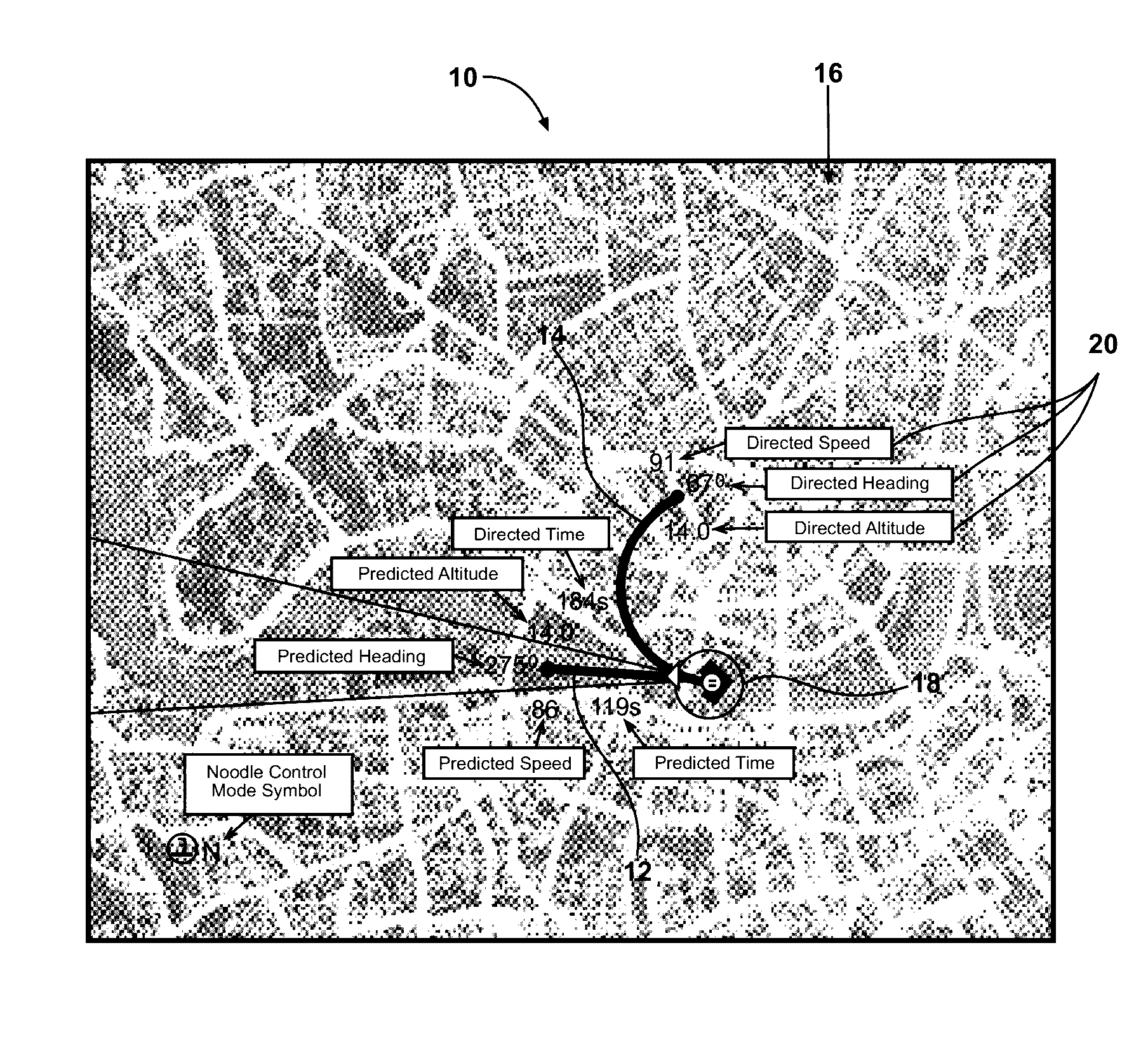
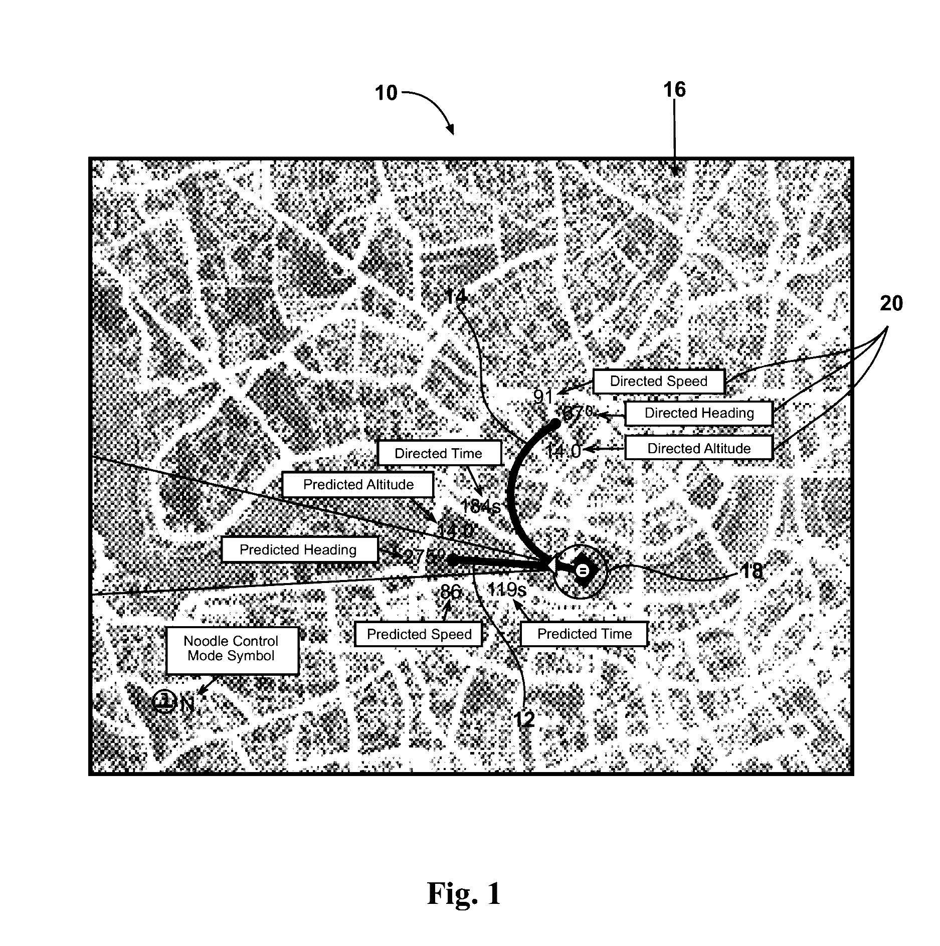
The present invention solves the problem of controlling multiple remotely piloted vehicles simultaneously. The invention provides a system and method for automating the control of an RPV by displaying a predicted future path of the RPV on a computer screen and allowing the pilot to adjust the future path using a directed noodle tool. This invention allows for more efficient and effective control of multiple RPVs.

Problems solved by technology

This is especially true for the tactical reconnaissance and close air support mission areas where tasks are often time critical, many relevant mission inputs and contextual parameters are not digitized, target / friendly / non-combatant identification is complex and variable, and mission objectives and conditions on the ground vary constantly.
Current methods to establish future path of vehicle movement are either too limited (e.g., employing fixed holding pattern) or require numerous selections to route planning systems (e.g., establishing future waypoints to navigate).
Such input methods are too rigid (resulting in a coarse path description, typically consisting of linear path segments connected by waypoints) or too time consuming when it is desirable to quickly designate future vehicle paths.

Method used


Image

  • Method and apparatus for operator supervision and direction of highly autonomous vehicles
  • Method and apparatus for operator supervision and direction of highly autonomous vehicles
  • Method and apparatus for operator supervision and direction of highly autonomous vehicles

Examples


Embodiment Construction

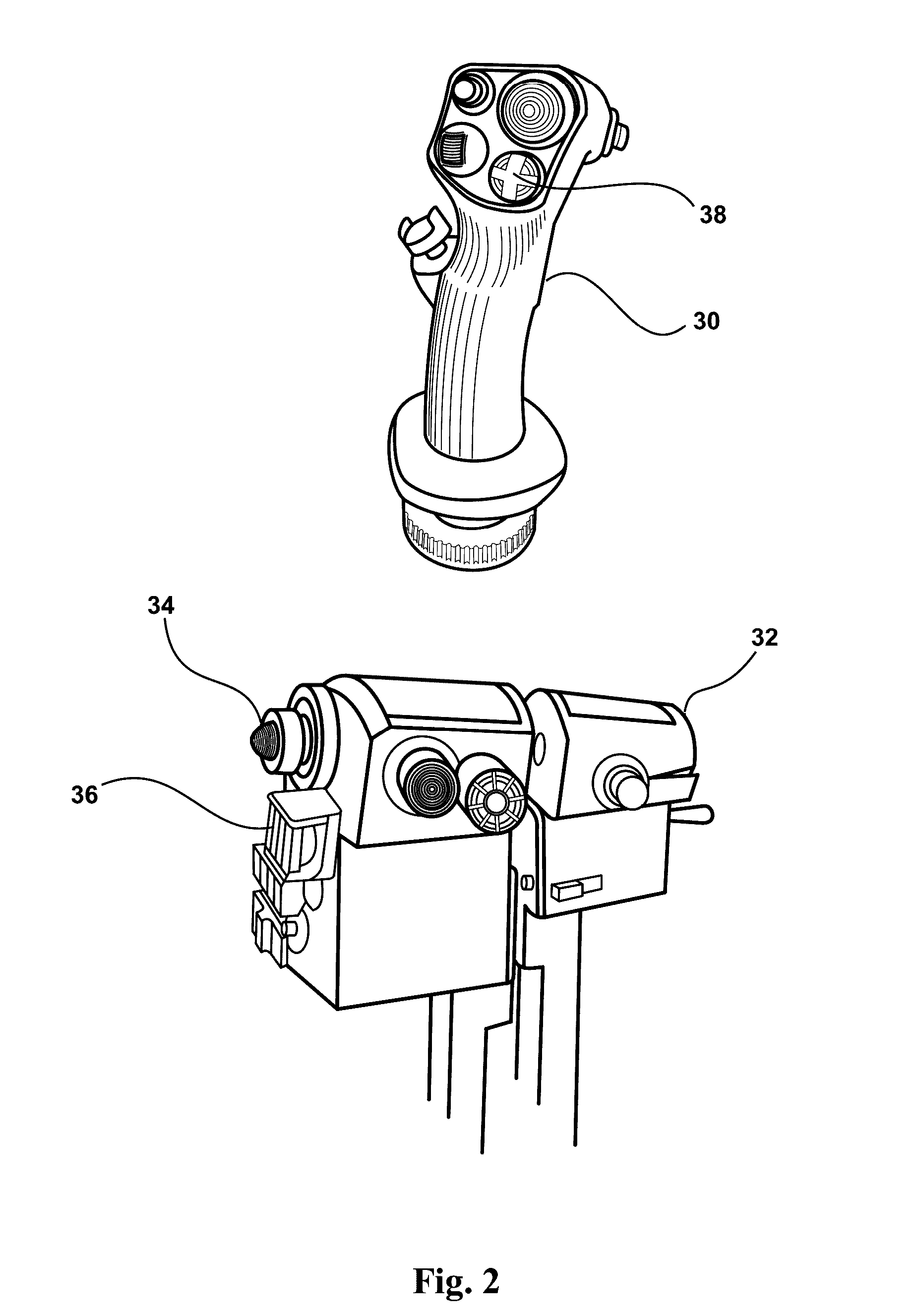
[0025]The invention disclosed herein allows vehicle operators to selectively allocate input devices between either real-time control of the vehicle, or to a new modality that graphically specifies a desired future path of the vehicle. The future path specification is rapid and allows arbitrary radius curves (to include straight-line paths) to be joined end-to-end, resulting in a far more precise and flexible configuration and adjustment of a desired future vehicle path. Particularly in applications in which operators' attention is divided across multiple other tasks (such as in control of multiple highly autonomous vehicles), this method enables control of a vehicle's near future path in situations that were previously rendered infeasible by pilot task saturation. In the disclosed invention, the resultant commanded path is progressively displayed to the operator as it is built, allowing adjustment at any point. Once the symbology and geometric indicators define the desired future pa...


PUM


Abstract

A system for automating the control of a Remotely Piloted Vehicle (RPV) includes a computer having a processor and a memory, a display operatively coupled to the computer and configured to display a future operating condition of the RPV and an input device operatively coupled to the computer. A predicted noodle tool is executed by the processor and configured to indicate a predicted future path of the RPV by generating a predicted noodle segment on the display. A directed noodle tool is executed by the processor to indicate a pilot-adjustable proposed future flight path of the RPV by generating a directed noodle segment on the display. Further, an input device mode selector is operatively coupled to the processor and configured to selectively map the input device to either manipulate a control surface of the RPV, or to manipulate the directed noodle segment.

Description

[0001]Pursuant to 37 C.F.R. §1.78(a)(4), this application claims the benefit of and priority to prior filed Provisional Application Ser. No. 61 / 835,860, filed 17 Jun. 2013, which is expressly incorporated herein by reference.RIGHTS OF THE GOVERNMENT[0002]The invention described herein may be manufactured and used by or for the Government of the United States for all governmental purposes without the payment of any royalty.FIELD OF THE INVENTION[0003]The present invention relates generally to apparatus and methods for controlling remotely piloted vehicles and, more particularly, to apparatus and methods for future route planning and execution of one or more remotely piloted vehicles.BACKGROUND OF THE INVENTION[0004]The success of Remotely Piloted Aircraft (or RPA) and Remotely Piloted Vehicles (RPVs) in recent military operations has led to increased interest in their capabilities and application to a variety of military missions (as well as civilian applications). For purposes of di...

Claims


Application Information

Patent Timeline
Patent Type & Authority Patents(United States)
IPC IPC(8): G05D1/00
CPCG05D1/0011G05D1/0027G05D1/0044
Inventor EGGERS, JEFFREYDRAPER, MARKSHAW, ROBERTHAMELL, JOSHUARUFF, HEATH
Owner THE UNITED STATES OF AMERICA AS REPRESETNED BY THE SEC OF THE AIR FORCE
Learn More