
Frame support for creating and displaying handmade paper crafts

Active Publication Date: 2017-01-10
OWENS CELENA MISSHOLA
View PDF87 Cites 5 Cited by
  • Summary
  • Abstract
  • Description
  • Claims
  • Application Information

AI Technical Summary

Benefits of technology

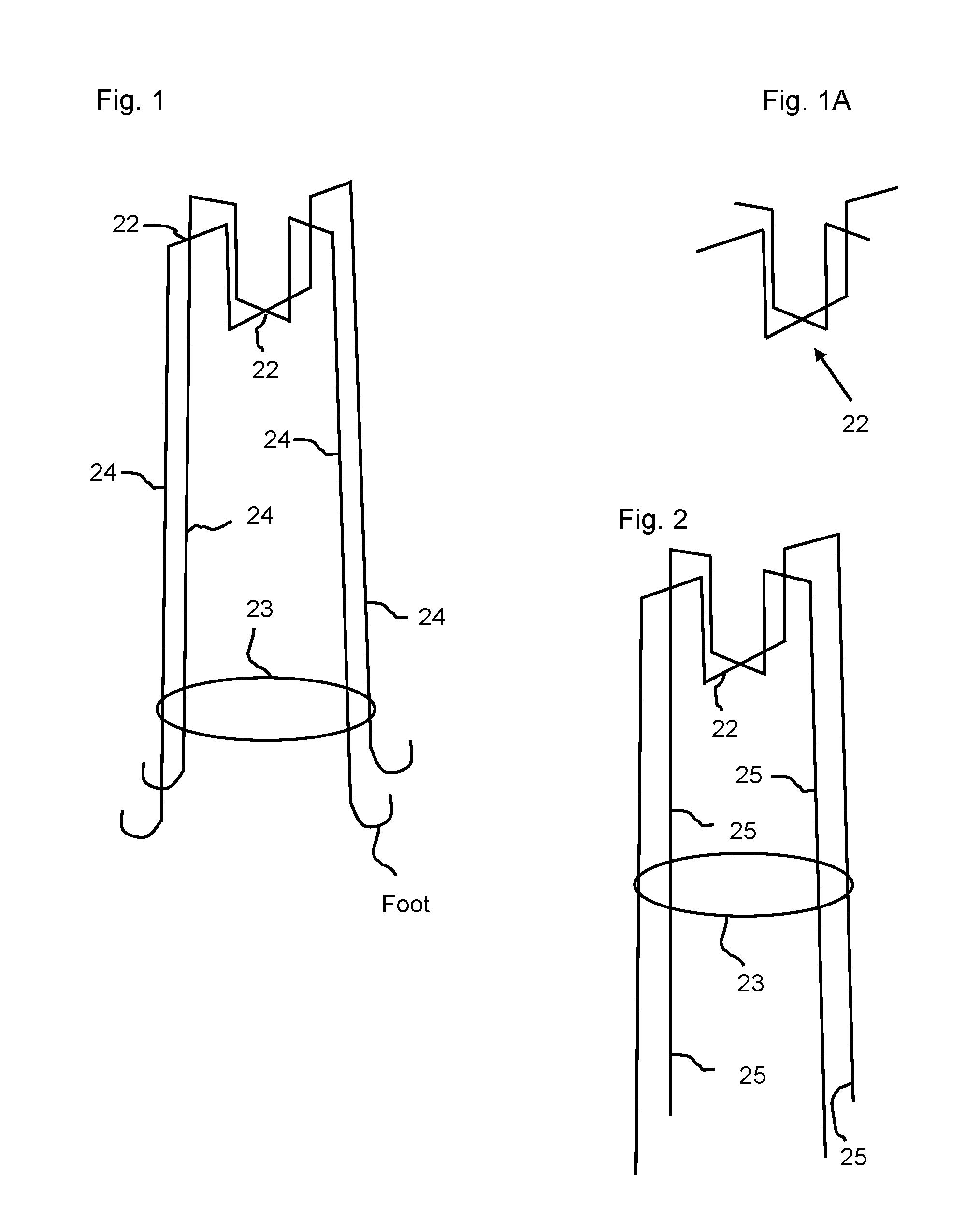
This patent describes a frame assembly for making handmade lanterns that are sturdy and durable. The frame is made up of sloping support members that can be adjusted with interchangeable parts to create different variations of the frame. The detachable support legs can be swapped out for different looks or replaced if one part breaks. The frame is also solid and long-lasting, making it a versatile and affordable option for creating lanterns.

Problems solved by technology

The problem is that if paper panels are damaged, they would have to be replaced professionally.
These lanterns may last for several uses, but they are fragile and have a very short life span.
Once the paper becomes faded or is torn, the lantern is no longer usable and has to be discarded.
Additionally, because these paper lanterns come in a specific permanent color, it may not be useful for subsequent events that have a different color scheme.
This design is not configured to enable one to change out the paper, or to reuse the frame to simply create one's own lantern.
Although handmade paper centerpieces and paper lanterns are typically simple to do, putting them on display is much more cumbersome.
These are flimsy and generally cannot stand erect on a table or on the ground.
This flimsy nature makes the DIY decoration look homemade and unsophisticated.
These handmade DIY lanterns do not have accommodations for a light source to be used, such as a tea light or an LED light.
If it is desired that the paper lantern stands erect and on its own, there is the risk of it slouching for lack of support.
Cardstock paper can be used to create a sturdier paper lantern that may stand on its own, but the paper thickness may limit the emitting of light through the paper.
This method is cumbersome and creates a lantern that has the paper permanently affixed to the frame, and cannot be disassembled for compact storage.
There is the WireFrames product sold online by AMACO in the year 2013 to present year (2014), http: / / www.amaco.com, that was designed to enable the user to create for all types of craft projects which may include a picture frame, candle holder, etc., however; this device is flimsy and does not stand on its own.
There are elastic cords provided to make the frame free standing, but these cords are not sturdy in its support, and are highly susceptible to breakage.
The frame is also too large to accommodate standard sized scrapbook paper and smaller.
This frame does not enable the paper to be elevated at various points along the frame.
This frame also does not provide a support for a candle or light source.
The above mentioned do not provide a way to create customized paper lanterns that can be infinitely redesigned with minimal effort.
These lanterns do not have interchangeable pieces that can create a variety of paper lantern frames.

Method used


Image

  • Frame support for creating and displaying handmade paper crafts
  • Frame support for creating and displaying handmade paper crafts
  • Frame support for creating and displaying handmade paper crafts

Examples


second embodiment

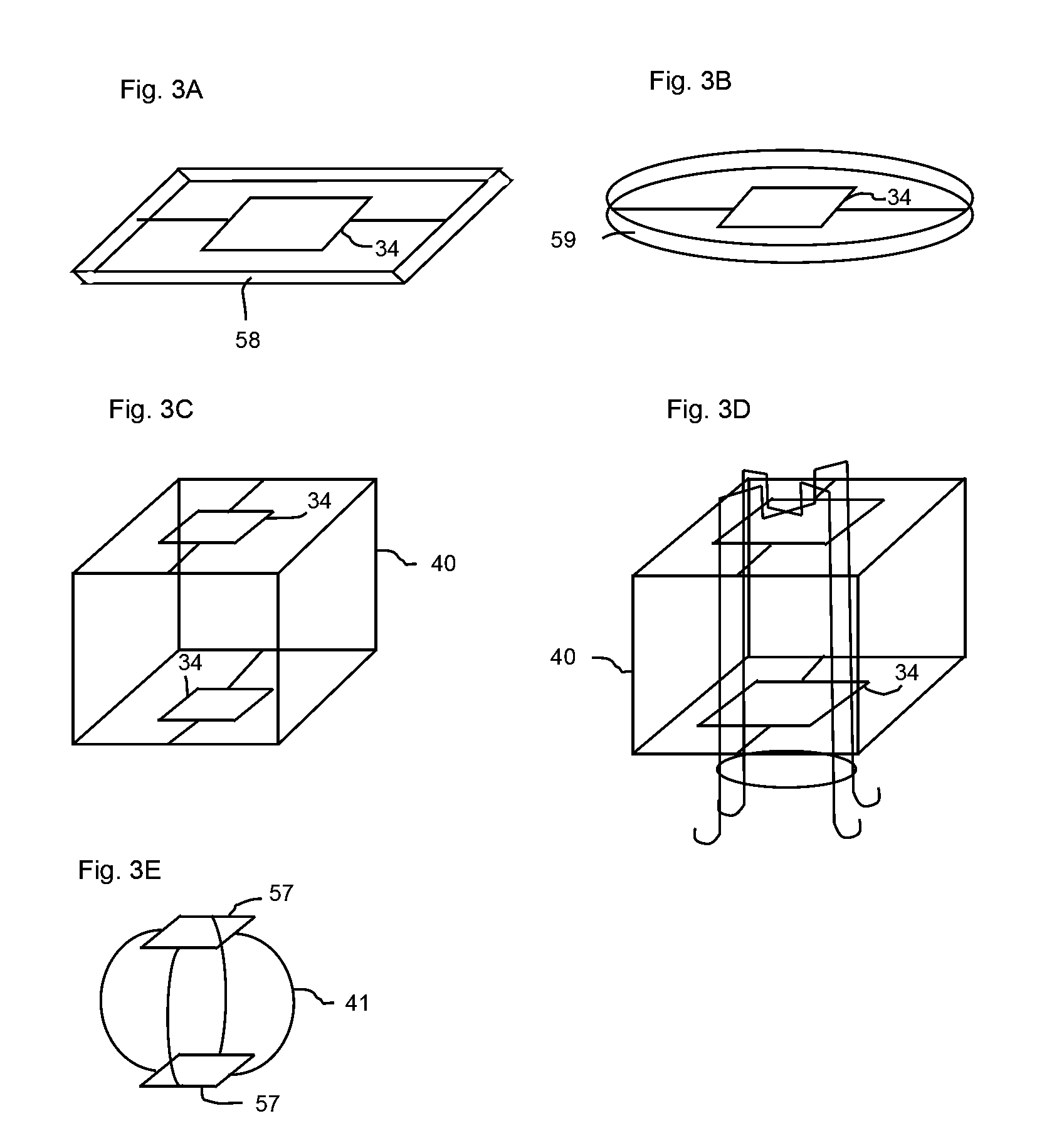
[0113]FIG. 4 is a second embodiment of a frame assembly comprising of a flange connector 42 and a plurality of detachable support legs 46, joined together to form a frame. Flange connector 42 contains a plurality of flanges 47, also seen in FIG. 4D, that extend out from the perimeter of the connector. The hollow center of flange 47 has a particular shape, which has at least one side, and comprises of a square, hexagon, octagon, flat, cross, etc. Detachable support leg 46 has an end, a contour plug 57 that plugs into flange 47 of connector 42. Contour plug 57 is the top horizontal portion of detachable support leg 46 that plugs directly into flange 47, as seen in FIG. 14D, going the majority of the way inside the flange. Contour plug 57 has a shaped end that corresponds with the hollow center of the flange, which comprises of a square, hexagon, octagon, flat, cross, etc. Detachable leg 46, preferably having a smooth cylindrical surface, comprised of contour plug 57, would most prefer...

third embodiment

[0170]FIG. 16B is the side view of a detachable support leg 76. Detachable support leg 76 is an alternate detachable support leg embodiment that comprises a round plug 86. Support leg 76 may come in various shapes and sizes and may have a plurality of round plugs 86. Unlike contour plug 57 found in FIGS. 14E-14F, round plug 86 is cylindrical in shape, and is made to be used with an extender connector 87, as illustrated in FIG. 16A. FIG. 16C is a frontal view of round plug 86. Extender connector 87 comprises a plurality of flanges 88. Flange 88 has a hollow cylindrical center, as seen in FIG. 16D. Flange 88 comprises of a leg spout 89 that extends downward like a spout. Leg spout 89 has curvature like a spout, to restrict support leg 76 from pivoting. Detachable support leg 76 is preferably made of a thin-rigid metal wire material, but any suitable material will do that produces similar results. The surface is smooth and cylindrical. Extender connector 87 is preferably made of a thin...


PUM


Abstract

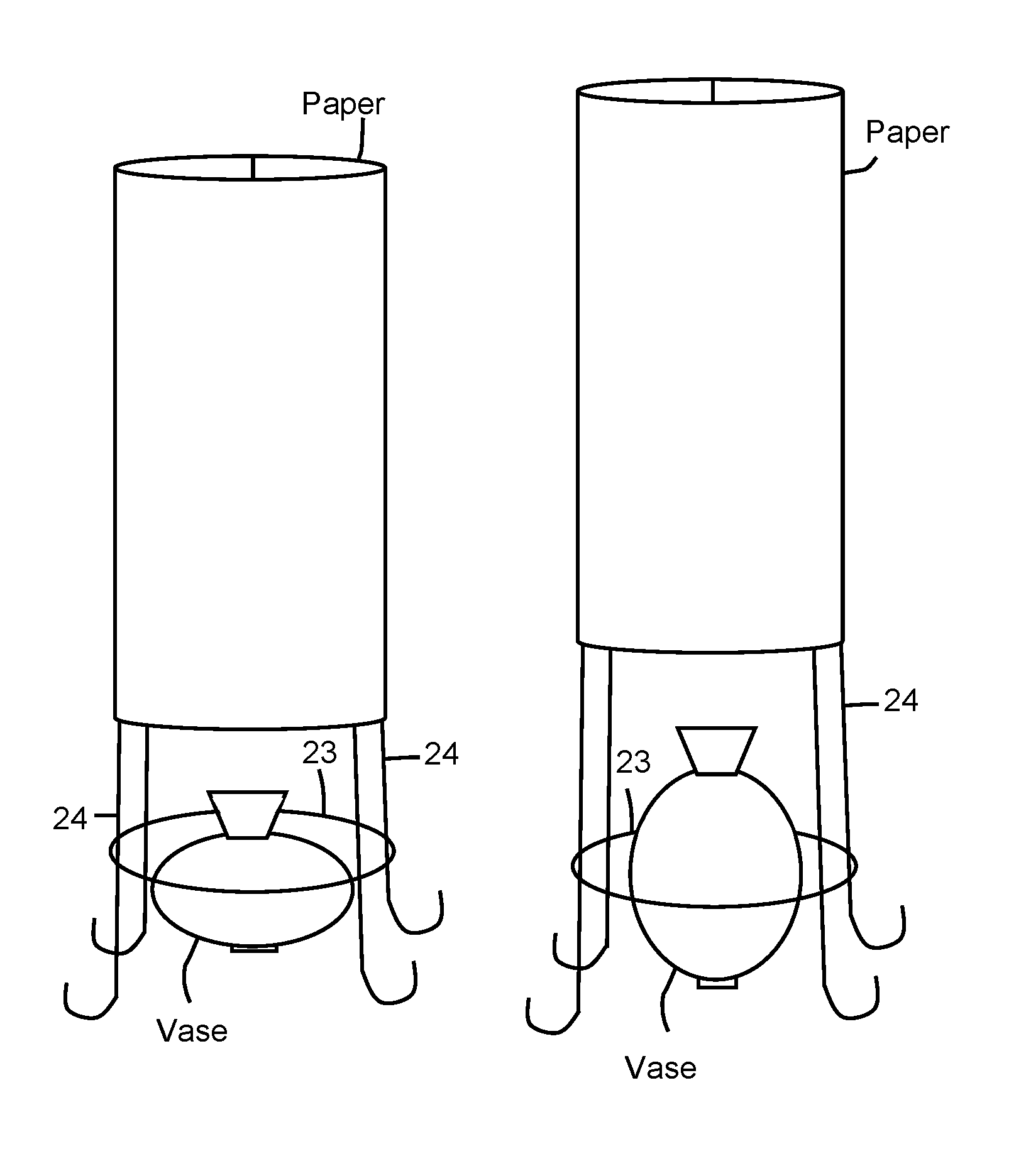
A frame and frame assembly for paper crafts and paper lanterns that is used to create handmade paper lanterns. Paper or similar material can be secured at various elevations along the frame enabling a variety styles and the ability to incorporate embellishments like small vases and bottles with the paper decoration. A frame assembly that has detachable members that can be used to create a variety of different configurations of lantern frames. Additional embodiments, such as a cage attachment is used to make the frame or frame assembly larger, to accommodate larger paper sizes or fabric. A magnet can be used with all embodiments to attach and / or secure a tea light or LED tea light to frame, to keep it secure.

Description

CROSS REFERENCE TO RELATED APPLICATIONS[0001]This application claims the benefit of provisional patent application Ser. No. 61 / 838,271, filed 2013 Jun. 22; 61 / 843,409 filed 2013 Jul. 7; and 61 / 979,498 filed 2014 Apr. 14, and non provisional patent application Ser No. 14 / 312,638, filed 2014 Jun. 23 by the present inventor.FEDERALLY SPONSORED RESEARCH[0002]Not Applicable.SEQUENCE LISTING, ETC ON CD[0003]Not Applicable.BACKGROUND[0004]Prior Art[0005]The following is a tabulation of some prior art that presently appears relevant:[0006]U.S. PatentsPatent NumberKind CodeIssue DatePatentee1,865,453A1932 Jul. 5Louis BaltzleyU.S. Pat. application PublicationsPublication No.Kind CodePubl. DateApplicant20050145760A12005 Jul. 7Necia Bower, Peter HellerForeign Patent DocumentCntryKindForeign Doc. No.CodeCodePub. DtApp or Patentee102062303CNA2011 May 18—201251093CNY2009 Jun. 03—102012111927DEB32013 Dec. 24Patentinhaber GleichNONPATENT LITERATURE DOCUMENTS[0007]Amaco, www.AMACO.com, “WireFrames Wi...

Claims


Application Information

Patent Timeline
IPC IPC(8): F16M11/22F21V35/00F21V19/00F21W121/00
CPCF16M11/22F21V35/003F21V19/0015F21W2121/00F21Y2101/02F21Y2115/10
Inventor OWENS, CELENA MISSHOLA
Owner OWENS CELENA MISSHOLA
Learn More