
Clamping device

a technology of clamping screw and sleeve, which is applied in the direction of hose connection, clothing, and household appliances, etc., can solve the problems of not being able to release the engagement again, can only be released again with considerable effort, and no longer suffice for other purposes of use, etc., to achieve easy production, increase the movement capability of the clamping screw, and increase the frictional force

Inactive Publication Date: 2017-01-31
NORMA GERMANY GMBH
View PDF13 Cites 1 Cited by
  • Summary
  • Abstract
  • Description
  • Claims
  • Application Information

AI Technical Summary

Benefits of technology

Enables quick diameter variation and high tension force application, simplifying the process of securing objects while maintaining ease of engagement and disengagement, enhancing the device's versatility beyond basic cable bundling.

Problems solved by technology

In most cases, this engagement cannot be released again or can only be released again with considerable effort.
In most cases, only a limited tension force can be applied radially inwards using the clamping band, which is easily sufficient for the consolidation of cables but may no longer suffice for other purposes of use.

Method used


Image

  • Clamping device
  • Clamping device
  • Clamping device

Examples


Embodiment Construction

[0035]The particulars shown herein are by way of example and for purposes of illustrative discussion of the embodiments of the present invention only and are presented in the cause of providing what is believed to be the most useful and readily understood description of the principles and conceptual aspects of the present invention. In this regard, no attempt is made to show structural details of the present invention in more detail than is necessary for the fundamental understanding of the present invention, the description taken with the drawings making apparent to those skilled in the art how the several forms of the present invention may be embodied in practice.

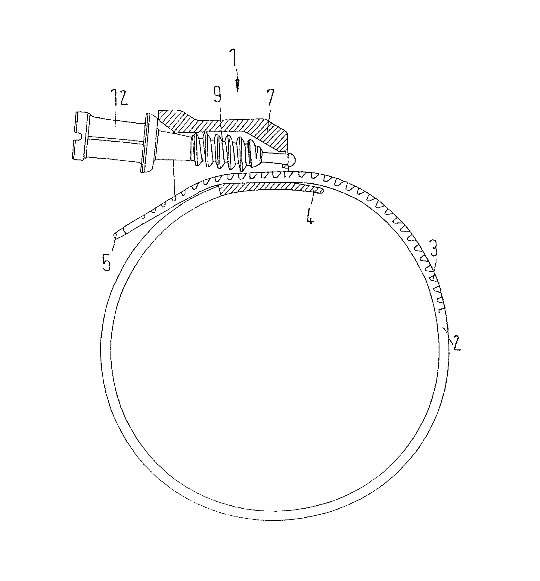
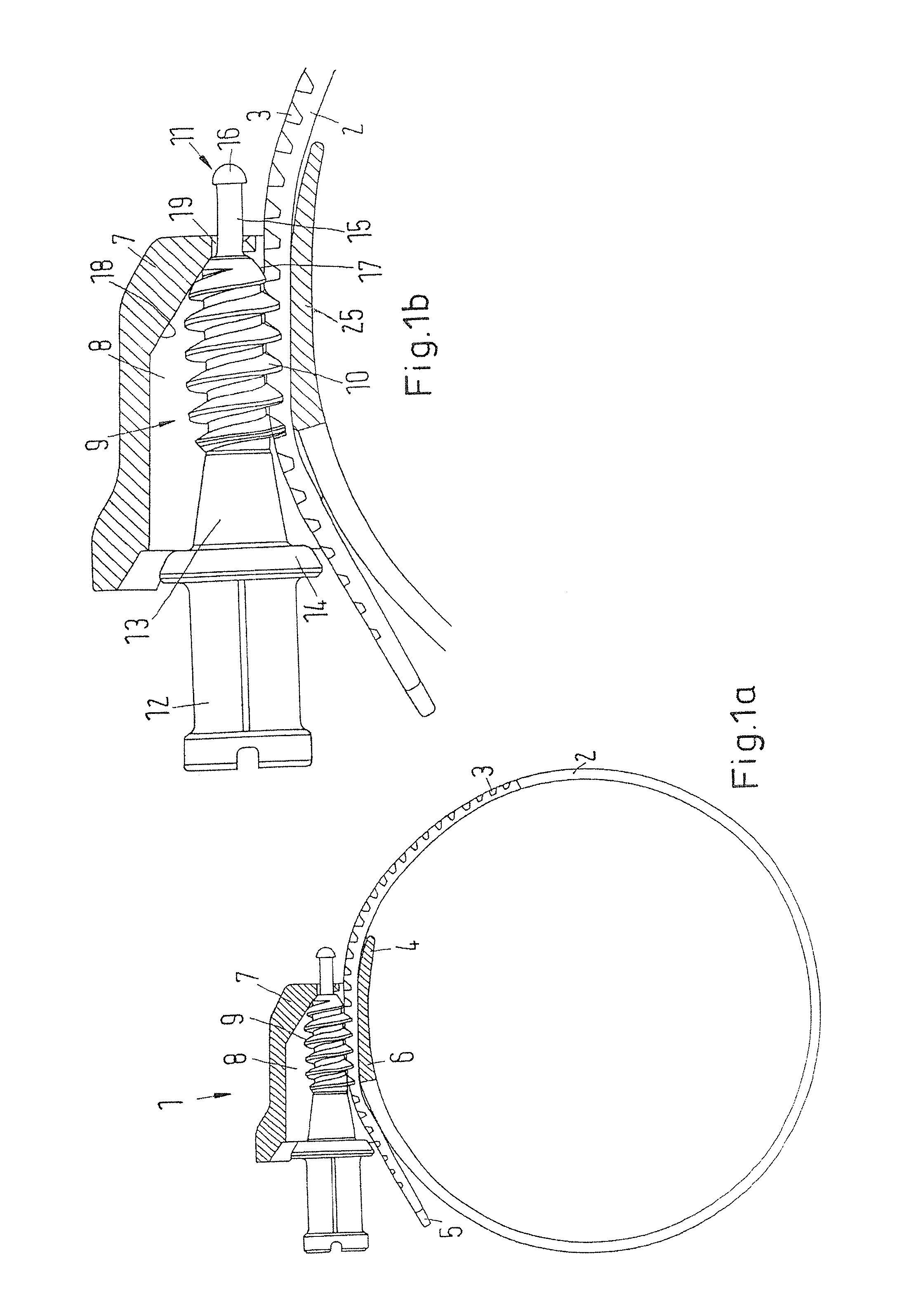
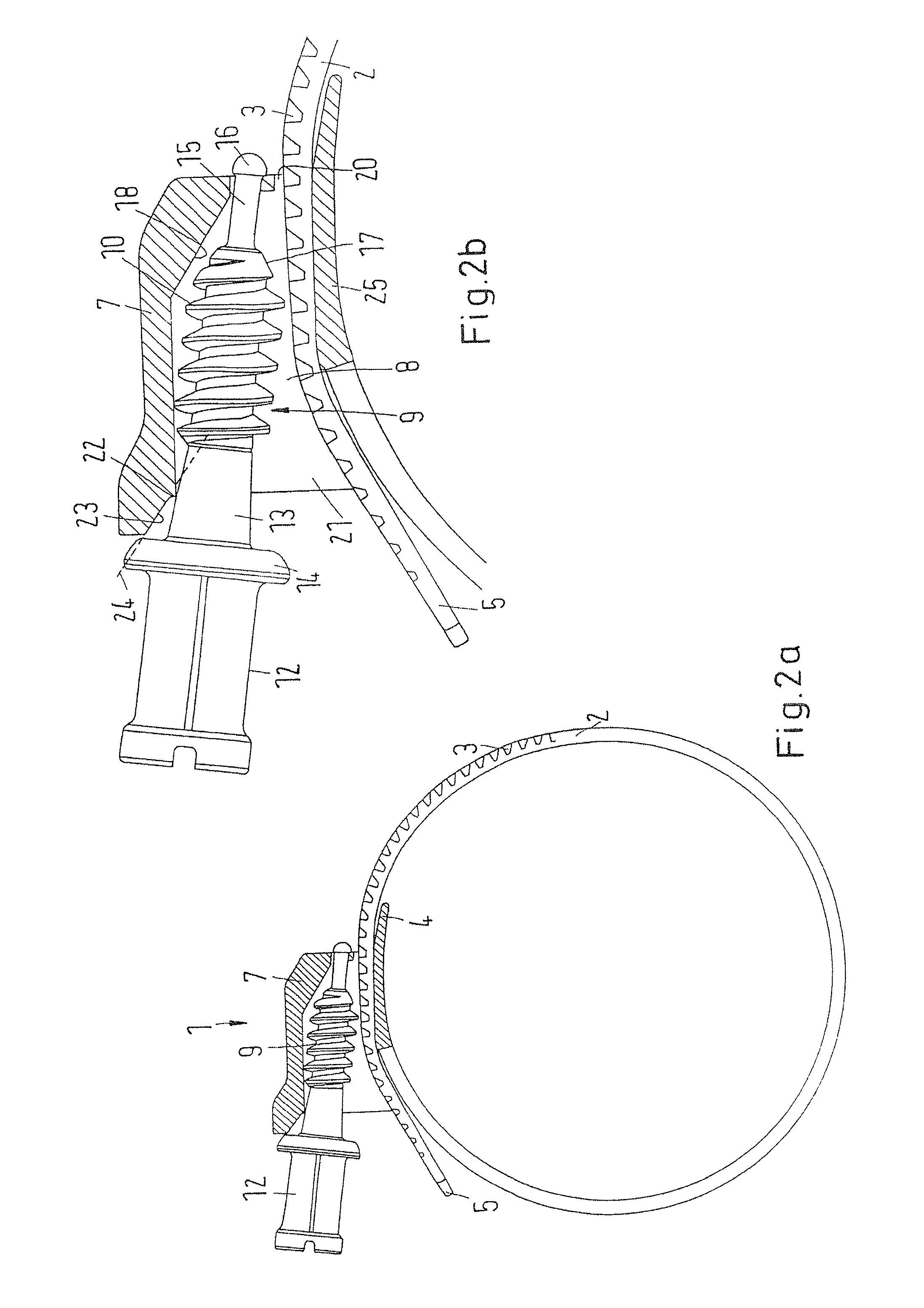
[0036]FIG. 1a shows a clamping device 1 in a schematic side view, partially in section. Clamping device 1 has a clamping band 2 that on a part of its radially outer surface has an engagement geometry which in the present case is embodied as an impressed thread, e.g., in the manner known from a worm drive clamp.

[0037]Clamp...


PUM

PropertyMeasurementUnit
flexibleaaaaaaaaaa
distanceaaaaaaaaaa
diameteraaaaaaaaaa

Abstract

Clamping device and method of connecting clamping device that includes a clamping band having a first end and a second end and an engagement geometry on at least one surface; and a tensioning head having a housing attached to the clamping band in the region of the first end and through which the second end of the clamping band is guidable, and an engagement element in the housing that is engageable with the engagement geometry. The engagement element is connected to the housing by a flexible connection, so that the engagement element is swivelable between a pull-through position, in which the clamping band may be pulled through the housing, and an engagement position, in which the clamping screw may engage with the engagement geometry.

Description

CROSS-REFERENCE TO RELATED APPLICATIONS[0001]The present application claims priority under 35 U.S.C. §119 of German Patent Application No. 10 2013 001 125.6, filed on Jan. 23, 2013, the disclosure of which is expressly incorporated by reference herein in its entirety.BACKGROUND OF THE INVENTION[0002]1. Field of the Invention[0003]The invention relates to a clamping device with a clamping band having a first end and a second end and a tensioning head having a housing attached to the clamping band in the region of the first end and through which the second end of the clamping band can be guided. The clamping band has an engagement geometry on at least one surface that can be engaged with an engagement element in the housing.[0004]2. Discussion of Background Information[0005]A clamping device of this type is for example used as a cable tie in order to consolidate a bundle of cables or lines or to attach a bundle of this type or only a single cable to a holder. For this purpose, the cla...

Claims


Application Information

Patent Timeline
Patent Type & Authority Patents(United States)
IPC IPC(8): F16L33/08
CPCF16L33/085F16L33/08Y10T24/1431Y10T29/49826
Inventor HENRICH, DETLEFKRAUSS, MATHIAS
Owner NORMA GERMANY GMBH
Features
  • Generate Ideas
  • Intellectual Property
  • Life Sciences
  • Materials
  • Tech Scout
  • Unparalleled Data Quality
  • Higher Quality Content
  • 60% Fewer Hallucinations
Learn More