Control mechanism for end-effector maneuver

a control mechanism and end-effector technology, applied in the field of robotics, can solve the problems of slow movement of the end-effector, less efficient maneuvering, and higher inertia

Active Publication Date: 2017-02-14
KURNIANTO DANIEL
View PDF9 Cites 172 Cited by
  • Summary
  • Abstract
  • Description
  • Claims
  • Application Information

AI Technical Summary

Problems solved by technology

This added weight leads to less efficient maneuvering, higher inertia, and slower movement of the end effector.
Again, the additional motor adds significant weight to the end effector affecting the moment of inertia, velocity, and acceleration of the end effector.
It uses a lengthy tube connected to the extruder to feed print filament which increases friction inside the tube, resulting in inefficient control of filament flow rate due to pushing and pulling motion on the filament along the tube.

Method used


Image

  • Control mechanism for end-effector maneuver
  • Control mechanism for end-effector maneuver
  • Control mechanism for end-effector maneuver

Examples


Embodiment Construction

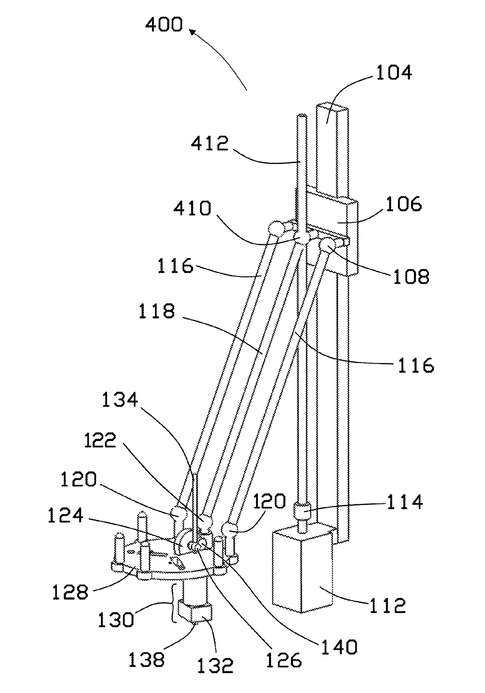
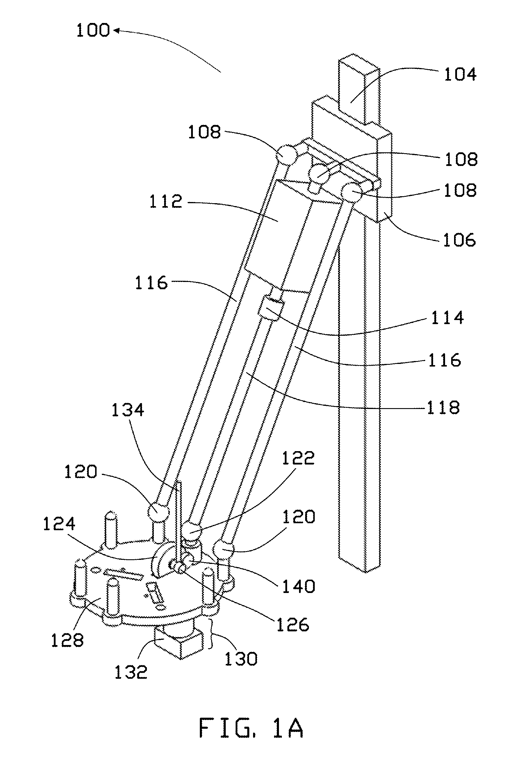
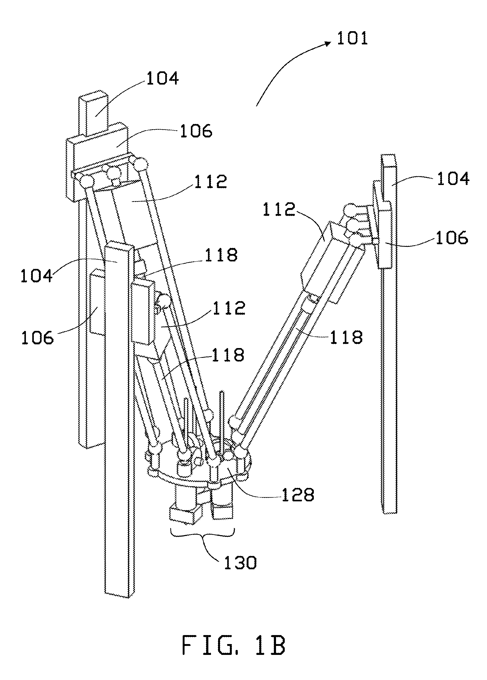
[0026]The detailed description set forth below in connection with the appended drawings is intended as a description of presently preferred embodiments of the invention and does not represent the only forms in which the present disclosure may be constructed and / or utilized. The description sets forth the functions and the sequence of steps for constructing and operating the invention in connection with the illustrated embodiments.

[0027]In referring to the description, specific details are set forth in order to provide a thorough understanding of the examples disclosed. In other instances, well-known methods, procedures, components and materials have not been described in detail as not to unnecessarily lengthen the present disclosure.

[0028]It should be understood that if an element or part is referred herein as being “on”, “against”, “in communication with”, “connected to”, “attached to” or “coupled to” another element or part, then it can be directly on, against, in communication wi...


PUM

PropertyMeasurementUnit
lengthaaaaaaaaaa
speedaaaaaaaaaa
weightaaaaaaaaaa

Abstract

A control mechanism for maneuvering an end effector is provided. The control mechanism comprises multiple actuator assemblies, multiple arm assemblies, and the end effector. Each of the multiple arm assemblies connect the end effector and the multiple actuator assemblies respectively. Each multiple actuator assemblies controls the movement of the multiple arm assemblies independently. One of the arm is rotated by a tool actuator where the rotating motion of the rotating arm drives a tool attached at the end effector. The control mechanism positions the tool actuator away from the end effector, thereby operating the tool at a remote location away from the end effector.

Description

BACKGROUND[0001]Field of the Invention[0002]The subject matter described herein relates generally to maneuvering robotics. More specifically, the present disclosure is related to a mechanism for maneuvering an end effector with delta robot arms.[0003]Description of Related Art[0004]Parallel robots, such as a delta robot, utilize multiple robotic arms to control orientation, motion, and placement of an end effector. Currently, most parallel robots uses actuators that are located at the base to maneuver the arms. The accuracy and efficiency maneuvering an end effector attached at one end of the robotic arms often relies on its overall structural design including center of mass and the mass itself.[0005]The centralized actuation mechanism and the light material and structure of the parallel robots enables the parallel robots to have high movement speed, fast acceleration, and little inertia. For such reasons, delta robots are being used in various applications and industries, such as 3...

Claims


Application Information

Patent Timeline
Patent Type & Authority Patents(United States)
IPC IPC(8): B29C47/10B25J9/04B25J9/00B29C47/00B25J15/00B25J9/02B29C47/08B29C47/86B29C67/00B33Y30/00B33Y10/00B29C48/05
CPCB25J9/02B25J9/003B25J9/023B25J9/04B25J15/0019B29C47/0014B29C47/0801B29C47/0813B29C47/1045B29C47/862B29C67/0051B29C67/0055B29C67/0085B25J9/0051B33Y10/00B33Y30/00Y10S901/02Y10S901/25Y10S901/41B25J9/0042B29C48/05B29C48/252B29C48/865B29C48/2552B29C48/2886B29C64/118B29C64/227B29C64/106
Inventor KURNIANTO, DANIEL
Owner KURNIANTO DANIEL
Why Eureka
Try Eureka