Ink-jet printer
a printer and inkjet technology, applied in the field of inkjet printers, can solve the problems of deteriorating print image quality and contamination inside the printer, and achieve the effects of reducing damage to the inkjet head, reducing print productivity, and increasing the temperature of the inkjet head
- Summary
- Abstract
- Description
- Claims
- Application Information
AI Technical Summary
Benefits of technology
Problems solved by technology
Method used
Image
Examples
first embodiment
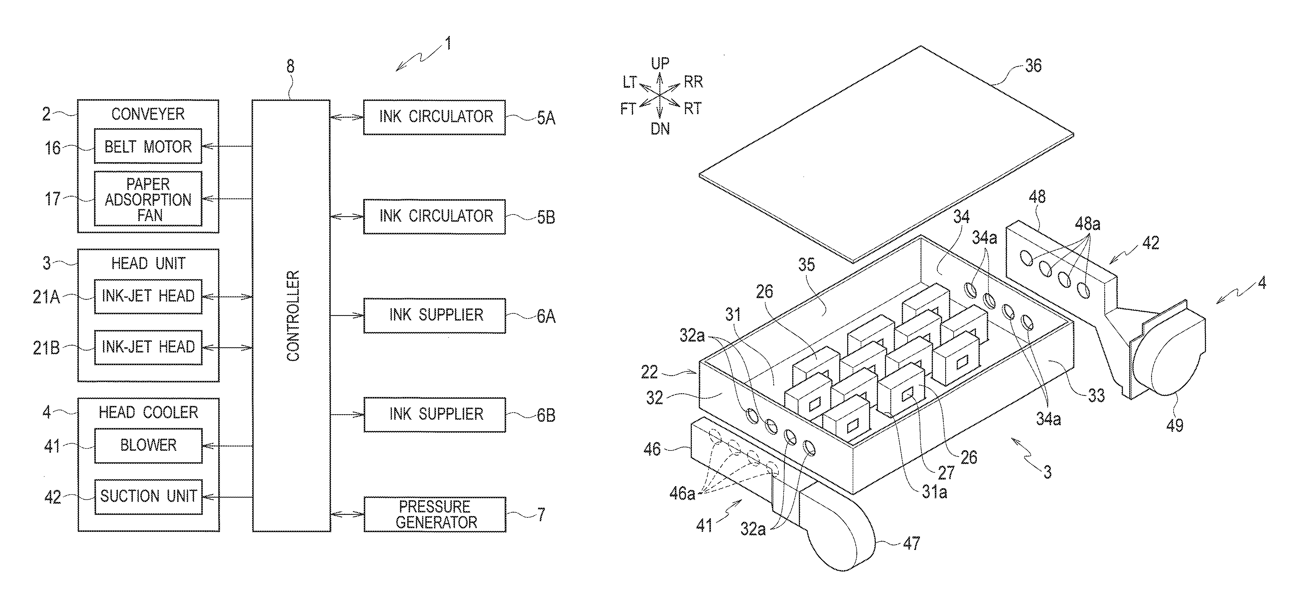
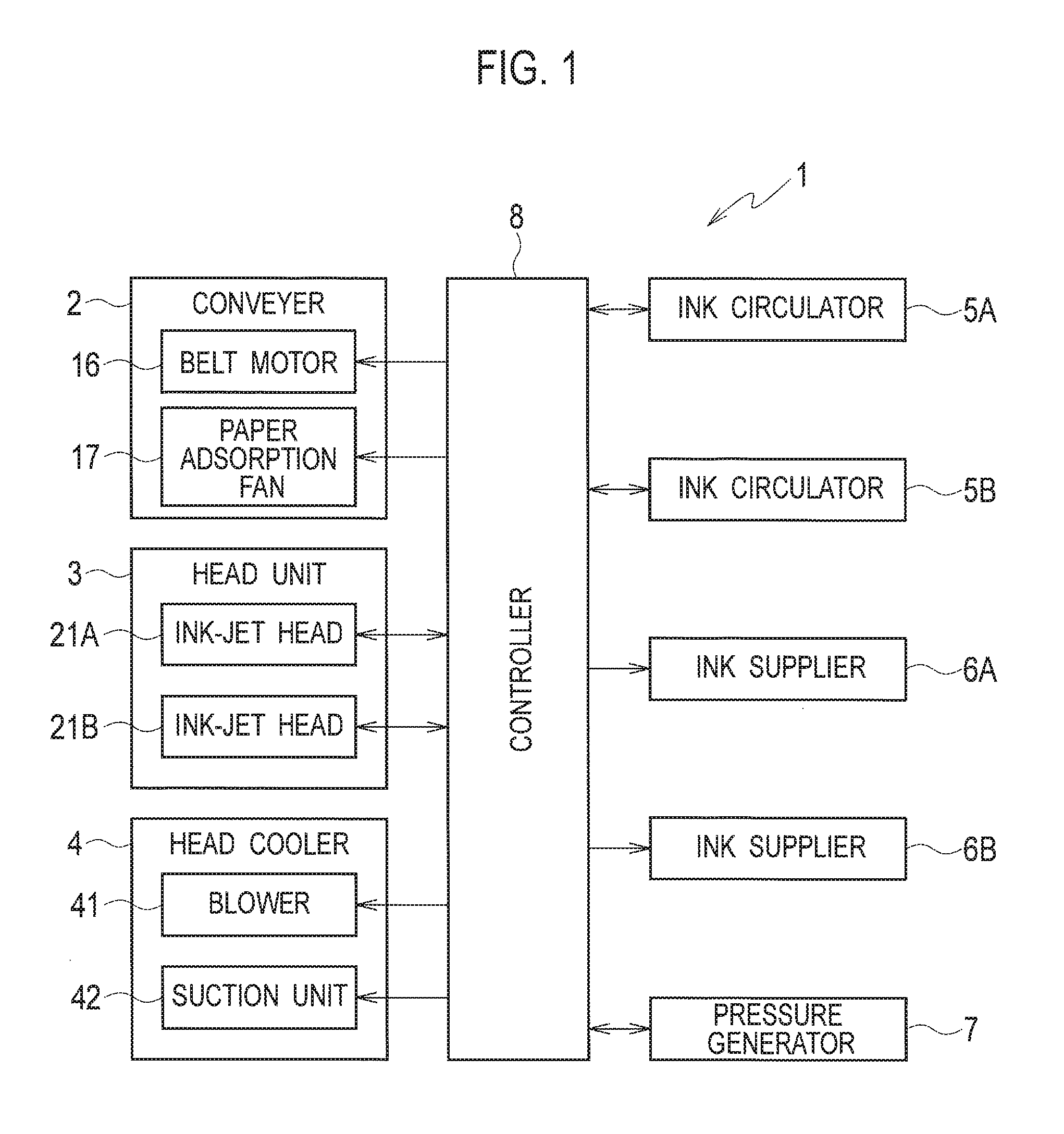
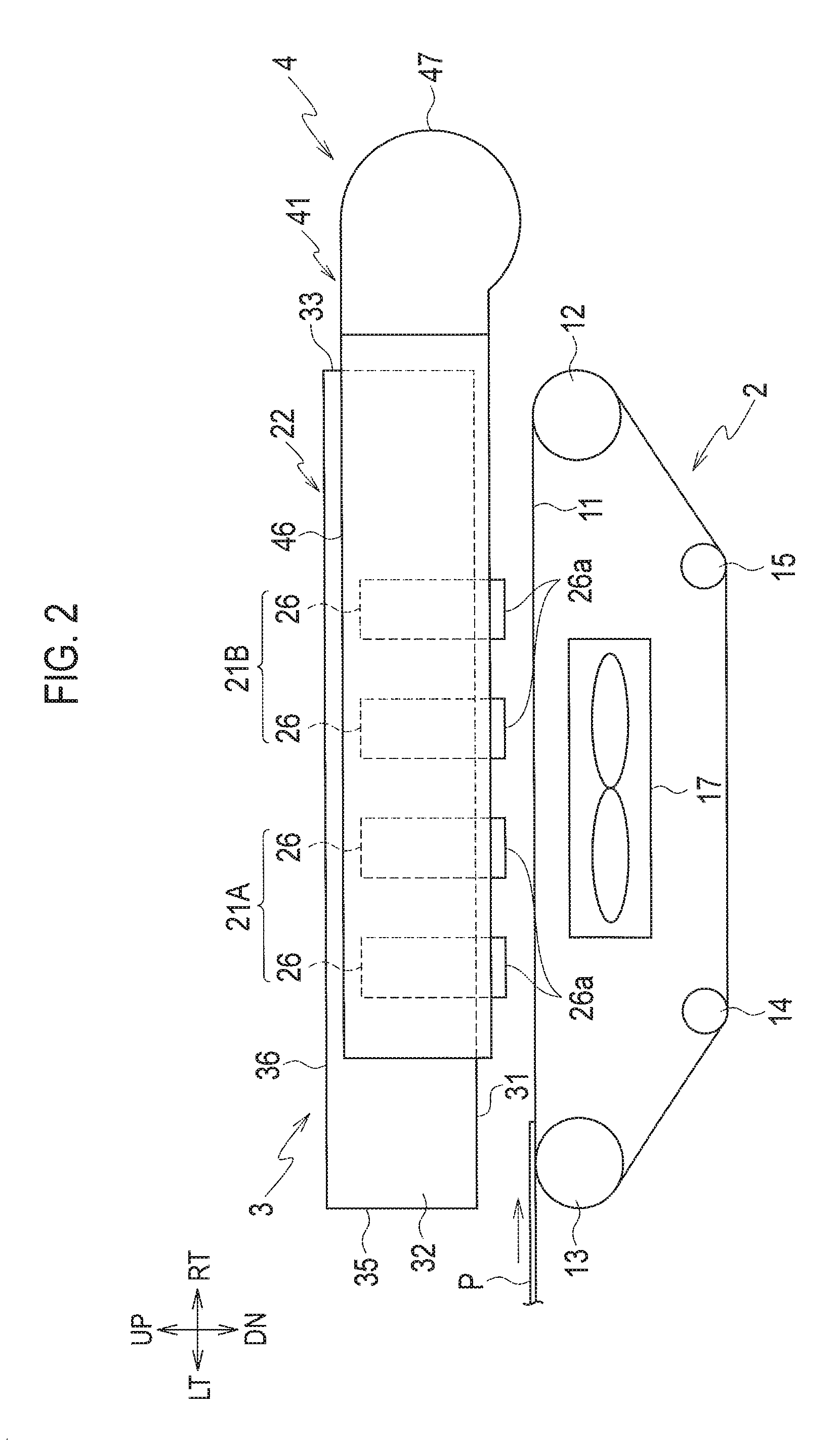
[0035]FIG. 1 is a block diagram showing a configuration of an ink-jet printer according to a first embodiment of the present invention. FIG. 2 is a schematic configuration diagram at a conveyer, a head unit and a head cooler in the ink-jet printer shown in FIG. 1. FIG. 3 is a plan view of the head unit and the head cooler. FIG. 4 is an exploded perspective view of the head unit and the head cooler. FIG. 5 is a cross-sectional view taken along the line V-V in FIG. 1. FIG. 6 is a schematic configuration diagram of an ink circulator, an ink supplier and a pressure generator in the ink-jet printer shown in FIG. 1.
[0036]In the following description, it is assumed that a direction perpendicular to the page surface in FIG. 2 is a longitudinal direction and a page surface front direction is the front. In FIGS. 2 to 6, 9A and 9B, the right direction, left, direction, up direction, down direction, front direction and rear direction are denoted by RT, LT, UP, DN, FT and RR, respectively. The d...
second embodiment
[0170]Next, description is given of a second embodiment in which changes are made to the operation of the image priority mode in the first embodiment described above. Note that an ink-jet printer of the second embodiment has the same structure as that of the ink-jet printer 1 of the first embodiment. Also, operations in a production priority mode according to the second embodiment are the same as those in the first embodiment, i.e., the operations in Steps S2 to S9 of FIG. 7.
[0171]FIG. 11 is a flowchart showing operations in an image priority mode in the second embodiment.
[0172]In Step S21 of FIG. 11, the controller 8 sets a paper conveyance seed for the image priority mode. To be more specific, the controller 8 sets a paper conveyance speed Vg for the image priority mode as a paper conveyance speed by the conveyer 2 during a print operation in the image priority mode. The paper conveyance speed Vg for the image priority mode is determined in advance to be lower than that in the pro...
third embodiment
[0178]Next, description is given of a third embodiment in which changes are made to the image priority mode in the first embodiment described above. Note that an ink-jet printer of the third embodiment has the same structure as that of the ink-jet printer 1 of the first embodiment. Also, operations in the production priority mode according to the second embodiment are the same as those in the first embodiment, i.e., the operations in Steps S2 to S9 of FIG. 7.
[0179]FIG. 12 is a flowchart showing operations in an image priority mode in the third embodiment.
[0180]The processing in Step S31 of FIG. 12 is the same as that in Step S10 of FIG. 8 described above.
[0181]Following Step S31, the controller 8 makes ink circulation settings for the image priority mode in Step S32. To be more specific, as set pressures by the pressure generator 7, the controller 8 sets a set pressure Pkg of a positive pressure-side pressure and a set pressure Pfg of a negative pressure-side pressure for the image ...
PUM
 Abstract
Description
Claims
Application Information
 - R&D
- Intellectual Property
- Life Sciences
- Materials
- Tech Scout
- Unparalleled Data Quality
- Higher Quality Content
- 60% Fewer Hallucinations
Browse by: Latest US Patents, China's latest patents, Technical Efficacy Thesaurus, Application Domain, Technology Topic, Popular Technical Reports.
© 2025 PatSnap. All rights reserved.Legal|Privacy policy|Modern Slavery Act Transparency Statement|Sitemap|About US| Contact US: help@patsnap.com


