Ink-jet printer

a printer and inkjet technology, applied in the field of inkjet printers, can solve the problems of deteriorating print image quality and contamination inside the printer, and achieve the effects of reducing damage to the inkjet head, reducing print productivity, and increasing the temperature of the inkjet head

Active Publication Date: 2016-08-25
RISO KAGAKU CORP
View PDF0 Cites 9 Cited by
  • Summary
  • Abstract
  • Description
  • Claims
  • Application Information

AI Technical Summary

Benefits of technology

[0018]According to the above configuration, in the second mode than, the ink temperature low to start cooling of the ink by the ink cooler is set lower than in the first mode, and thereby an increase in the temperature of the ink-jet head can be reduced. Thus, even in the second mode having a smaller flow rate of the cooling air than the first mode, the damage to the ink-jet head can be reduced without a drop in print productivity.

Problems solved by technology

The ink mist causes contamination inside the printer.
Also, the ink mist may deteriorate print image quality by adhering to paper to be printed.

Method used


Image

  • Ink-jet printer
  • Ink-jet printer
  • Ink-jet printer

Examples


first embodiment

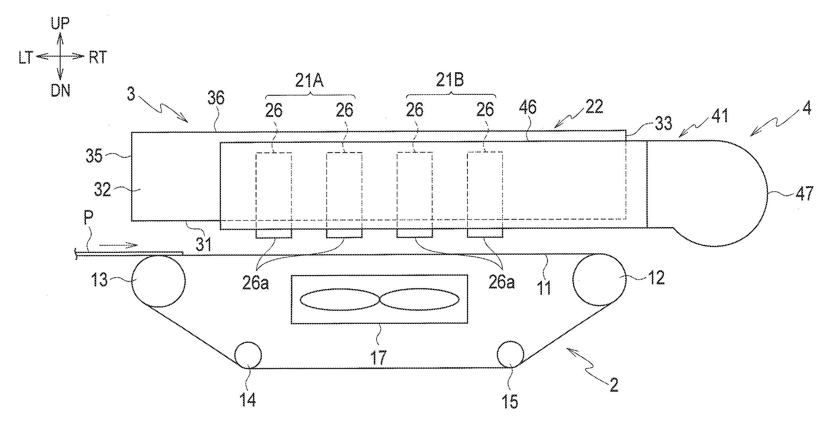
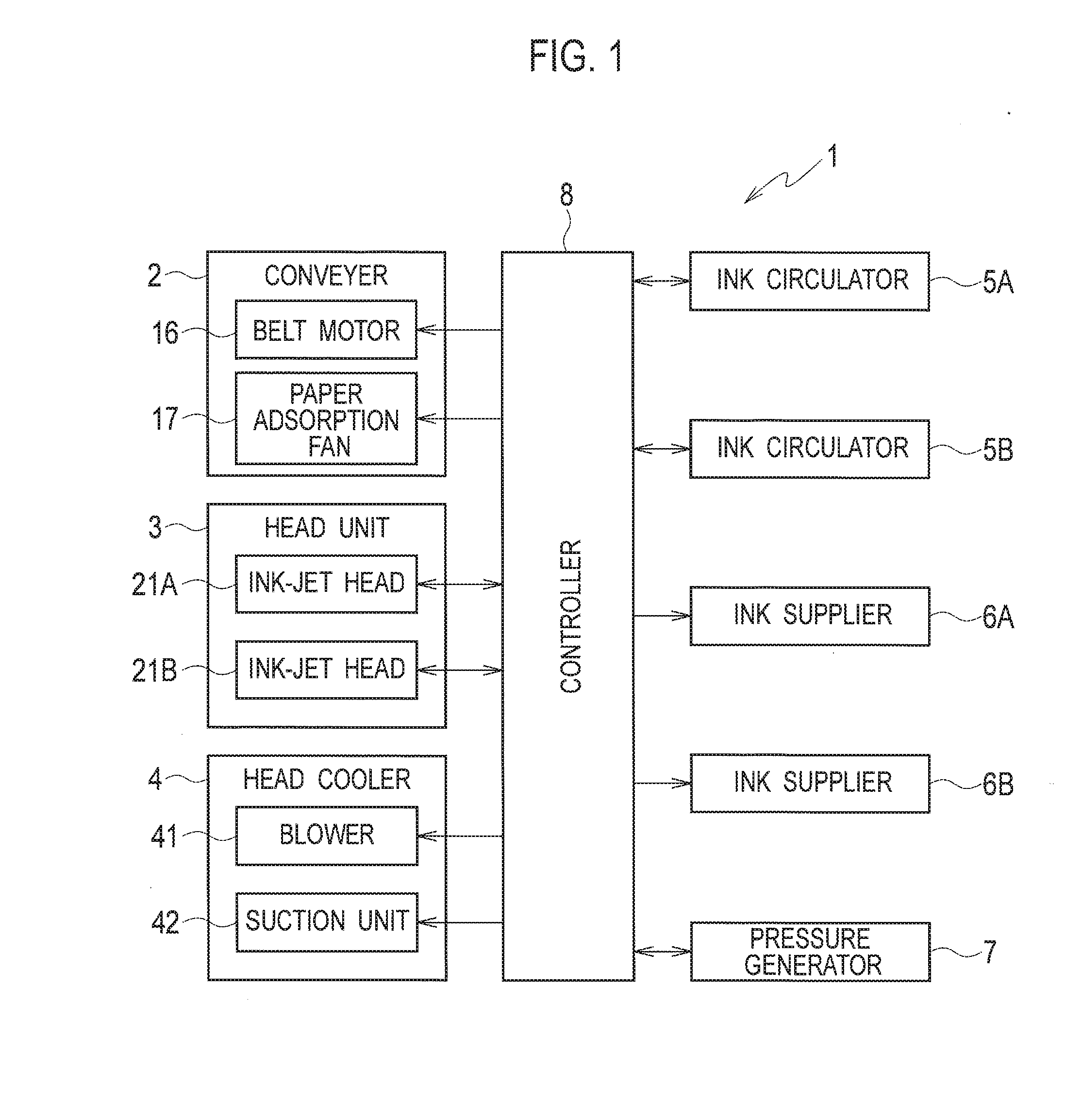
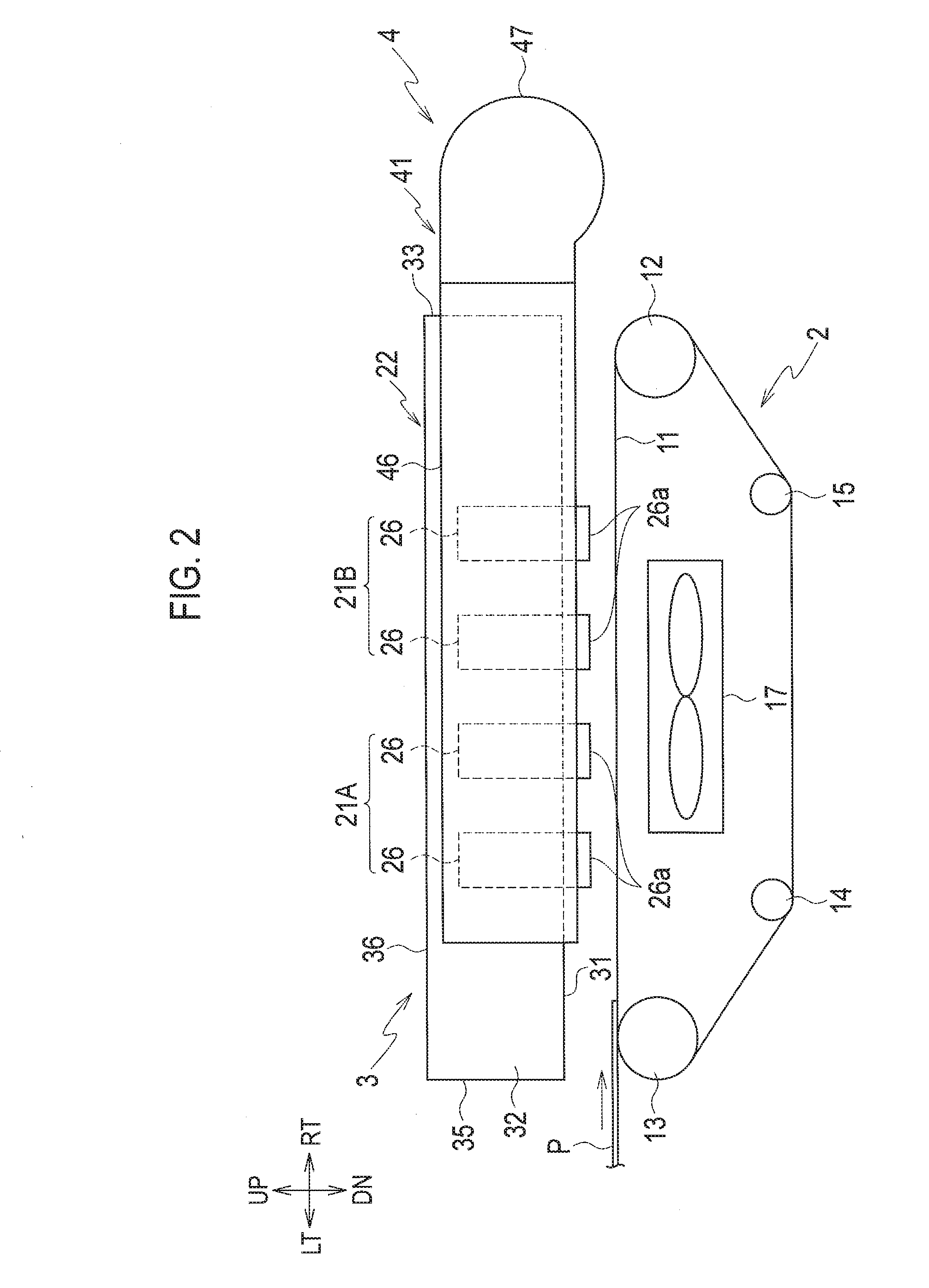
[0035]FIG. 1 is a block diagram showing a configuration of an ink-jet printer according to a first embodiment of the present invention. FIG. 2 is a schematic configuration diagram at a conveyer, a head unit and a head cooler in the ink-jet printer shown in FIG. 1. FIG. 3 is a plan view of the head unit and the head cooler. FIG. 4 is an exploded perspective view of the head unit and the head cooler. FIG. 5 is a cross-sectional view taken along the line V-V in FIG. 1. FIG. 6 is a schematic configuration diagram of an ink circulator, an ink supplier and a pressure generator in the ink-jet printer shown in FIG. 1.

[0036]In the following description, it is assumed that a direction perpendicular to the page surface in FIG. 2 is a longitudinal direction and a page surface front direction is the front. In FIGS. 2 to 6, 9A and 9B, the right direction, left, direction, up direction, down direction, front direction and rear direction are denoted by RT, LT, UP, DN, FT and RR, respectively. The d...

second embodiment

[0170]Next, description is given of a second embodiment in which changes are made to the operation of the image priority mode in the first embodiment described above. Note that an ink-jet printer of the second embodiment has the same structure as that of the ink-jet printer 1 of the first embodiment. Also, operations in a production priority mode according to the second embodiment are the same as those in the first embodiment, i.e., the operations in Steps S2 to S9 of FIG. 7.

[0171]FIG. 11 is a flowchart showing operations in an image priority mode in the second embodiment.

[0172]In Step S21 of FIG. 11, the controller 8 sets a paper conveyance seed for the image priority mode. To be more specific, the controller 8 sets a paper conveyance speed Vg for the image priority mode as a paper conveyance speed by the conveyer 2 during a print operation in the image priority mode. The paper conveyance speed Vg for the image priority mode is determined in advance to be lower than that in the pro...

third embodiment

[0178]Next, description is given of a third embodiment in which changes are made to the image priority mode in the first embodiment described above. Note that an ink-jet printer of the third embodiment has the same structure as that of the ink-jet printer 1 of the first embodiment. Also, operations in the production priority mode according to the second embodiment are the same as those in the first embodiment, the operations in Steps S2 to S9 of FIG. 7.

[0179]FIG. 12 is a flowchart showing operations in an image priority mode in the third embodiment.

[0180]The processing in Step S31 of FIG. 12 is the same as that in Step S10 of FIG. 8 described above.

[0181]Following Step S31, the controller 8 makes ink circulation settings for the image priority mode in Step S32. To be more specific, as set pressures by the pressure generator 7, the controller 8 sets a set pressure Pkg of a positive pressure-side pressure and a set pressure Pfg of a negative pressure-side pressure for the image priori...


PUM


Abstract

A head holder has an opening through which a space between the head holder and a conveyer communicates with an inside of the head holder. A head cooler includes a blower configured to blow air into the head holder from an outside of the head holder with a flow rate of blow air and a suction unit configured to suction air from the head holder with a flow rate of suction air. The head cooler generates cooling air for cooling an ink-jet head inside the head holder by the blower and the suction unit. A controller controls the flow rate of blow air and the flow rate of suction air such that air containing ink mist is suctioned into the head holder through the opening.

Description

CROSS REFERENCE TO RELATED APPLICATION[0001]This application is based upon and claims the benefit of priority from the prior Japanese Patent Application No. 2015-035087, filed on Feb. 25, 2015, the entire contents of which are incorporated herein by reference.BACKGROUND[0002]1. Technical Field[0003]The present disclosure relates to an ink-jet printer configured to perform printing by ejecting ink from an ink-jet head.[0004]2. Related Art[0005]In an ink-jet printer, ink mist is generated by ink ejection from an ink-jet head. The ink mist causes contamination inside the printer. Also, the ink mist may deteriorate print image quality by adhering to paper to be printed.[0006]To counter this problem, Japanese Patent Application Publication No. 2004-284058 discloses an ink-jet printer including a mist collector. The mist collector in the ink-jet printer sets a collection duct at a negative pressure by a sirocco fan, and collects ink mist by suctioning air containing the ink mist through a...

Claims


Application Information

Patent Timeline
Patent Type & Authority Applications(United States)
IPC IPC(8): B41J13/00B41J29/377
CPCB41J13/0009B41J29/377B41J2/1714B41J2002/1853B41J2/04515B41J2/18B41J2/245B41J2202/12B41J2/175B41J29/38
Inventor OTSUKA, SHINICHIROKUBOTA, HIROHITO
Owner RISO KAGAKU CORP
Why Eureka
Try Eureka