
Invertible timer mount for camera

a timer mount and camera technology, applied in the field of cameras, can solve problems such as distortion, inconsistency, or un-matching frames in video or photographs

Inactive Publication Date: 2017-03-07
GOPRO
View PDF7 Cites 42 Cited by
  • Summary
  • Abstract
  • Description
  • Claims
  • Application Information

AI Technical Summary

Benefits of technology

The patent text describes an invertible timer mount system for cameras that allows for panoramic capture in a variety of rotational directions. The system includes a housing, a drive shaft, a panning mechanism, and two mount components. The first mount component is designed to secure to a camera, while the second mount component is designed to secure to a camera mount component. The system can be easily converted between configurations without the need for a tool set. The technical effect of this invention is to provide a flexible and convenient way to capture panoramic videos or photographs in a variety of rotational directions.

Problems solved by technology

Using today's camera systems, capturing a high-quality panoramic video or photograph can be difficult for a user, resulting in distortion, inconsistencies, or un-matching frames in the video or photograph.

Method used


Image

  • Invertible timer mount for camera
  • Invertible timer mount for camera
  • Invertible timer mount for camera

Examples


Embodiment Construction

[0013]The figures and the following description relate to preferred embodiments by way of illustration only. It should be noted that from the following discussion, alternative embodiments of the structures and methods disclosed herein will be readily recognized as viable alternatives that may be employed without departing from the principles of what is claimed.

[0014]Reference will now be made in detail to several embodiments, examples of which are illustrated in the accompanying figures. It is noted that wherever practicable similar or like reference numbers may be used in the figures and may indicate similar or like functionality. The figures depict embodiments of the disclosed system (or method) for purposes of illustration only. One skilled in the art will readily recognize from the following description that alternative embodiments of the structures and methods illustrated herein may be employed without departing from the principles described herein.

Overview Configuration

[0015]I...


PUM


Abstract

A timer mount system is configured for use with a camera and a camera mount to capture panoramic videos or photographs in multiple rotational directions. The timer mount system comprises a housing, a drive shaft, a panning mechanism, a first mount component, and a second mount component. Within the housing, the drive shaft is coupled to the panning mechanism, which stores rotational energy when wound in a rotational direction and then causes the drive shaft to rotate in a reverse rotational direction when released. The first mount component is configured to secure to and rotate with the drive shaft, while the second mount component is configured to remain stationary while allowing the drive shaft to rotate freely. A first configuration allows the first mount component to rotate in a first rotational direction, and a second configuration allows the first mount component to rotate in a second rotational direction.

Description

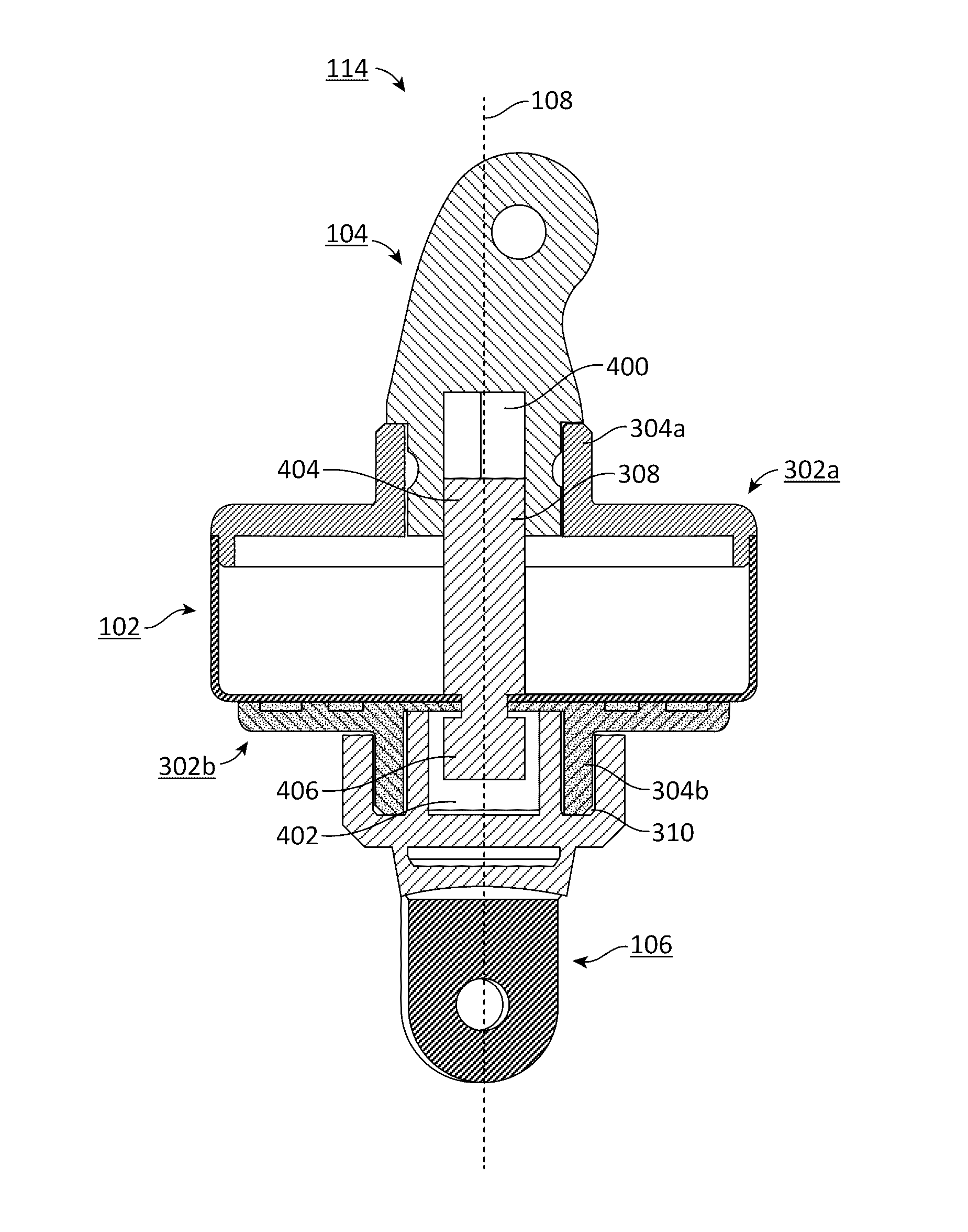
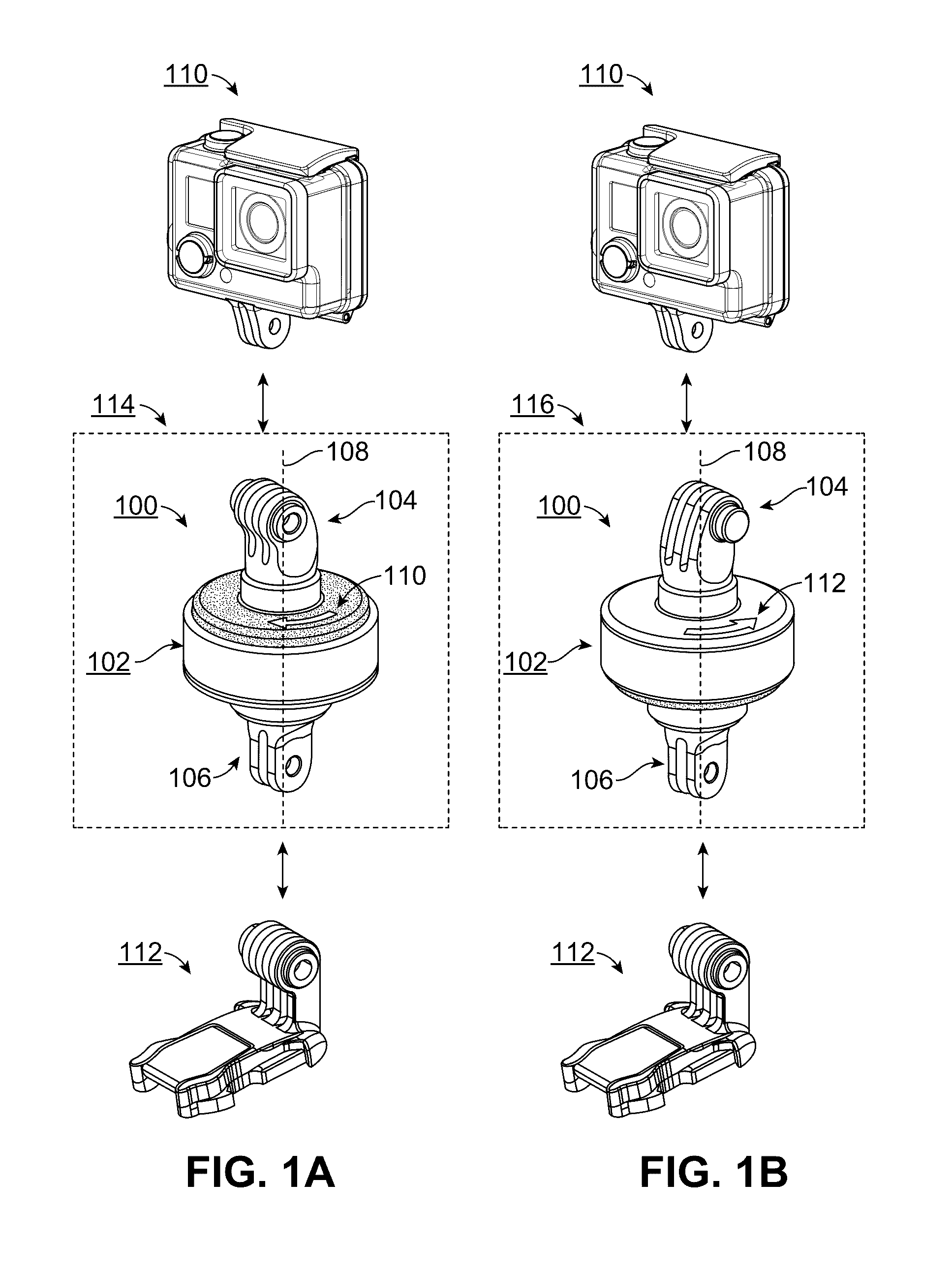
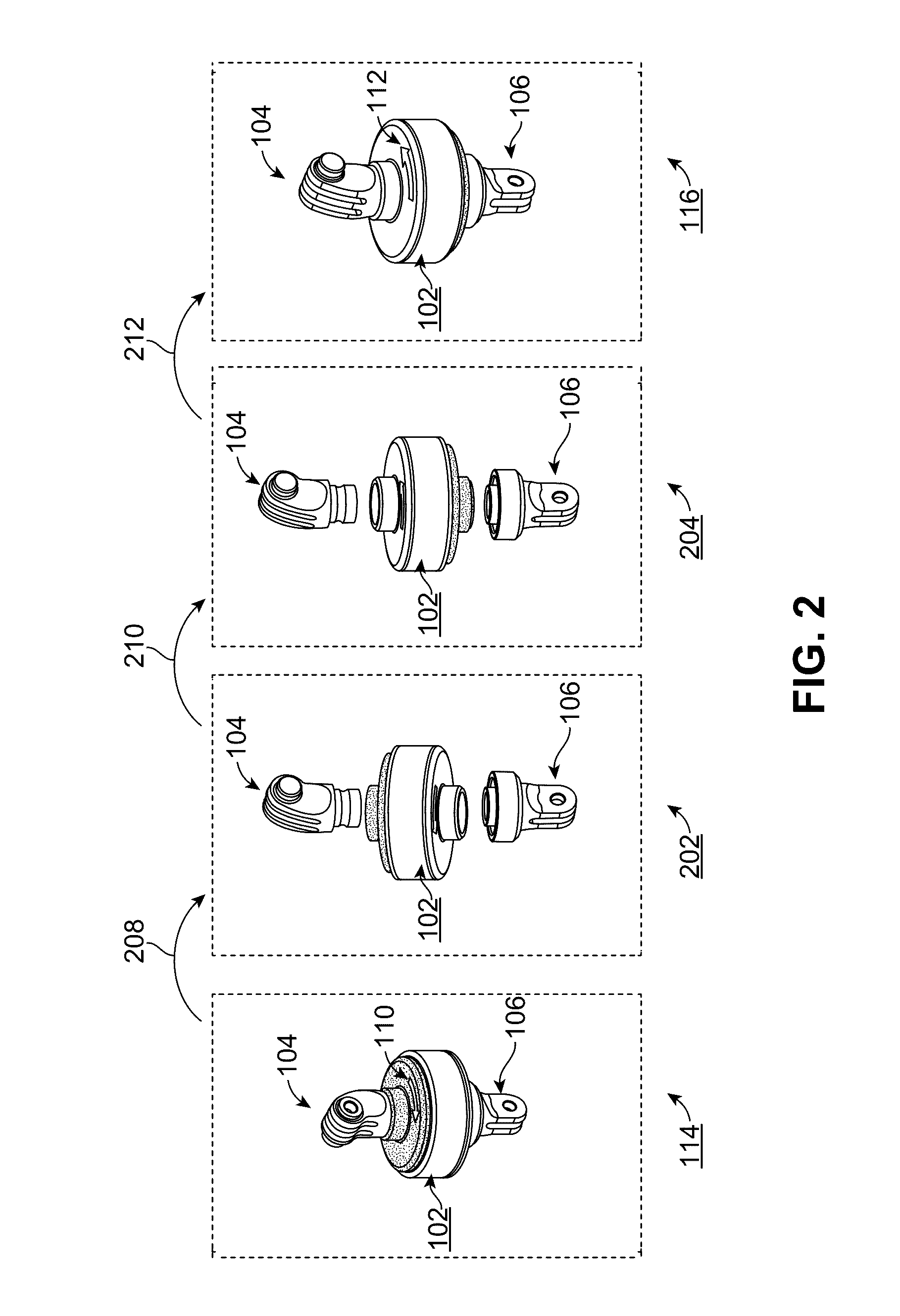
BACKGROUND[0001]Technical Field[0002]This disclosure relates to cameras, and more specifically, to an invertible timer mount for a camera.[0003]Description of the Related Art[0004]Digital cameras are increasingly used in outdoors and sports environments. Sometimes, it is desirable to capture a video or a photograph with a very wide-angle or panoramic view in these environments. Using today's camera systems, capturing a high-quality panoramic video or photograph can be difficult for a user, resulting in distortion, inconsistencies, or un-matching frames in the video or photograph.BRIEF DESCRIPTIONS OF THE DRAWINGS[0005]The disclosed embodiments have other advantages and features which will be more readily apparent from the following detailed description of the invention and the appended claims, when taken in conjunction with the accompanying drawings, in which:[0006]FIG. 1a illustrates a first configuration of an invertible timer mount system, according to one embodiment.[0007]FIG. 1...

Claims


Application Information

Patent Timeline
Patent Type & Authority Patents(United States)
IPC IPC(8): G03B37/02F16M11/20G03B17/56F16M11/08H04N5/232
CPCG03B17/561F16M11/2014G03B37/02H04N5/23238F16M11/18F16M13/00H04N23/698
Inventor HARRISON, RYAN
Owner GOPRO
Learn More