

Switching regulator and control circuit and control method therefor
a technology of switching regulator and control circuit, applied in the direction of electric variable regulation, process and machine control, instruments, etc., can solve the problems of different control effects on performance, off of the switch, audio noise,
- Summary
- Abstract
- Description
- Claims
- Application Information
AI Technical Summary
Benefits of technology
Problems solved by technology
Method used
Image

Examples
first embodiment
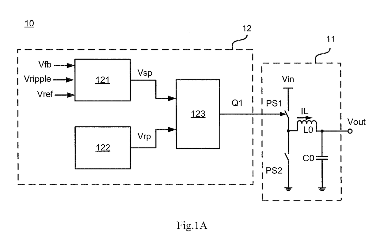
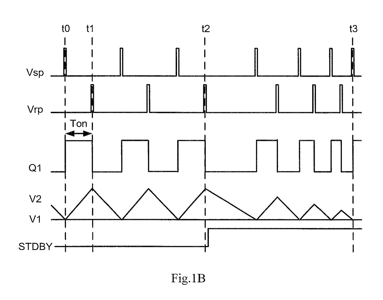
[0031]FIG. 1A is a schematic diagram of a switching regulator in accordance with the present disclosure. As shown in FIG. 1A, switching regulator 10 comprises power stage 11 and control circuit 12. Power stage 11 comprises power switch PS1, rectifying element PS2, inductive element L0 and filtering element C0. In the present disclosure, a power switch in a power stage refers to a switch which is turned on periodically so that energy flows into the inductive element, and the energy is stored by the inductive element in a DC-DC regulator. A rectifying element / switch refers to an element or a switch which is turned on periodically so that energy flows to a load.
[0032]In the present embodiment, power switch PS1 may be any controlled semiconductor switching device, such as Metal-Oxide-Semiconductor Field Effect Transistor (MOSFET) and Insulated Gate Bipolar Transistor (IGBT) etc. Rectifying element PS2 is electrically coupled to power switch PS1. In the present embodiment, rectifying ele...
second embodiment
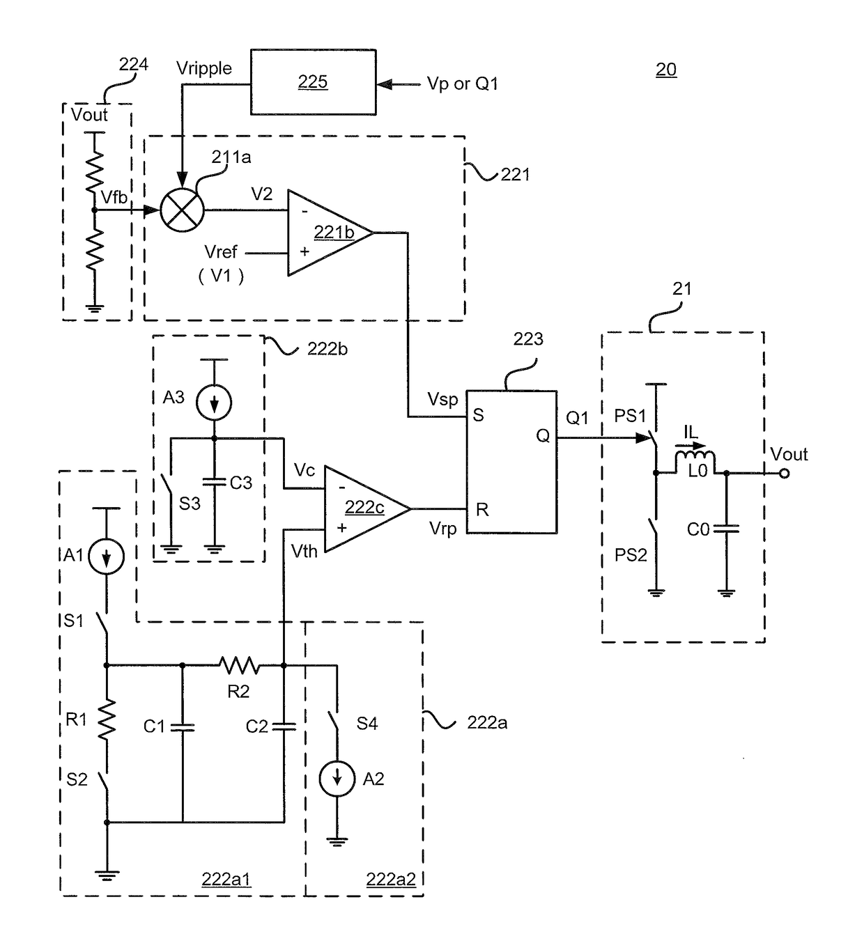
[0045]FIG. 2A is a schematic diagram of a switching regulator in accordance with the present disclosure. In the present embodiment, switching regulator 20 comprises power stage 21 and control circuit 22. Wherein, the structure of power stage 21 is substantially the same with the corresponding circuit shown in FIG. 1A, and will not be illustrated herein. It is to be understood by those skilled in the art that power stage 21 may adopt other well-known circuit topologies such as a boost topology and a buck-boost topology as necessary.
[0046]Control circuit 22 comprises set pulse generator 221, reset pulse generator 222 and logic circuit 223. Preferably, control circuit 22 further comprises feedback circuit 224 and ripple generator 225.
[0047]Set pulse generator 221 comprises superimposing circuit 221a and first comparing circuit 221b.
[0048]By voltage division, feedback circuit 224 outputs feedback voltage Vfb proportional to output voltage Vout to superimposing circuit 221a. Ripple gene...
third embodiment
[0080]FIG. 5 is a schematic diagram of a switching regulator in accordance with the present disclosure. In the present embodiment, switching regulator 50 comprises power stage 51 and control circuit 52. Wherein, power stage 51 adopts a boost topology. It may be understood by those skilled in the art that power stage 51 may adopt well-known circuit topologies such as a buck topology and a buck-boost topology as necessary.
[0081]It is the same with the first embodiment and the second embodiment that control circuit 52 comprises set pulse generator 521, reset pulse generator 522 and logic circuit 523. Meanwhile, set pulse generator 522 and logic circuit 523 adopt same circuits with that of the second embodiment.
[0082]Comparing to the second embodiment, set pulse generator 521 in the present embodiment comprises a current control loop 521a and voltage control loop 521b. Voltage control loop 521b receives feedback voltage Vfb proportional to output voltage Vout and outputs error voltage V...
PUM
 Abstract
Description
Claims
Application Information