Control circuit and control method of buck-boost converter, and buck-boost converter using the same

A control circuit and control method technology, applied in control/regulation systems, DC power input conversion to DC power output, instruments, etc., can solve problems such as frequency hopping, audio noise generation, and slow dynamic response

Active Publication Date: 2018-05-29
SILERGY SEMICON TECH (HANGZHOU) CO LTD
View PDF4 Cites 0 Cited by
  • Summary
  • Abstract
  • Description
  • Claims
  • Application Information

AI Technical Summary

Problems solved by technology

[0009] In view of this, the object of the present invention is to provide a novel control method and control circuit of a buck-boost converter to solve the problem of large output voltage fluctuations and frequency jumps in the prior art when operating mode switching and light load conditions , slow dynamic response, low efficiency, and technical problems such as audio noise

Method used


Image

  • Control circuit and control method of buck-boost converter, and buck-boost converter using the same
  • Control circuit and control method of buck-boost converter, and buck-boost converter using the same
  • Control circuit and control method of buck-boost converter, and buck-boost converter using the same

Examples


Embodiment Construction

[0085] Several preferred embodiments of the present invention will be described in detail below with reference to the accompanying drawings, but the present invention is not limited to these embodiments. The present invention covers any alternatives, modifications, equivalent methods and schemes made on the spirit and scope of the present invention. In order to provide the public with a thorough understanding of the present invention, specific details are set forth in the following preferred embodiments of the present invention, but those skilled in the art can fully understand the present invention without the description of these details.

[0086] The invention can be embodied in various forms, some examples of which are described below.

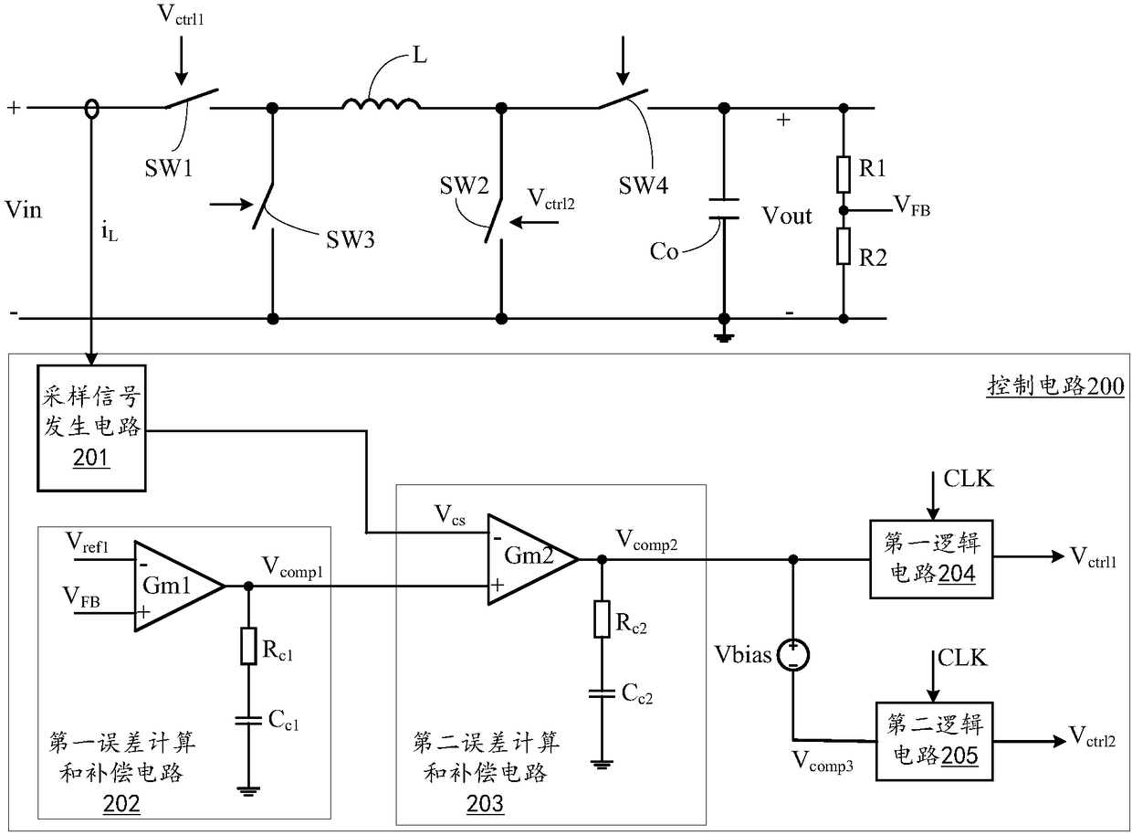
[0087] refer to Figure 2A , shows a functional block diagram of the control circuit 200 of the buck-boost converter according to the first embodiment of the present invention. According to this embodiment, the control circuit 200 is use...


PUM


Abstract

The invention discloses a control circuit and a control method for a buck-boost converter, which samples the inductor current and generates a current sampling signal based on it; controls the receiving current sampling in the rising time interval of the inductor current in each switching cycle signal; from the moment when the inductor current rises to the peak value of the inductor current to the end of the current switching cycle, the maximum value of the current sampling signal is maintained to generate a sampling signal; the inductor current is limited by the second reference signal representing the maximum value information of the inductor current Peak value, so that the inductor current will not fluctuate too much, so the fluctuation of the output voltage will be relatively reduced; at the same time, the feedback control loop can adjust the switching device according to the real-time error information between the compensation signal and the voltage signal representing the inductor current Therefore, the dynamic response speed of the system is faster, shortening the time required to return to a stable state again improves the dynamic response speed, stability and reliability of the system.

Description

technical field [0001] The invention relates to the field of switching power supplies, and more specifically, to a control circuit and a control method for a buck-boost converter. Background technique [0002] Buck-boost converters, such as four-switch buck-boost converters, are widely used in the fields of electric power, communications, and electronic instruments due to their advantages of in-phase input and output, low switching loss, and adjustable output voltage. The optimal control strategy of the switch has also become a hotspot of current research. [0003] refer to Figure 1A , shows the block diagram of a buck-boost converter. The buck-boost converter includes two parts, a power stage circuit 11 and a control and drive circuit 12; wherein, the power stage circuit 11 receives the input voltage Vin, and generates a stable output voltage Vout at the output terminal to drive the load; the control and drive circuit 12 to generate the corresponding control and drive si...

Claims


Application Information

Patent Timeline
Patent Type & Authority Patents(China)
IPC IPC(8): H02M3/156H02M3/158
CPCH02M3/156H02M3/158H02M3/1566
Inventor 罗迪
Owner SILERGY SEMICON TECH (HANGZHOU) CO LTD
Why Eureka
Try Eureka