Switching device for disconnecting a current path

A technology of switching devices, current paths, applied in the direction of electronic switches, electrical components, pulse technology, etc., capable of solving problems such as deformation schemes that cannot be solved in a satisfactory manner

Active Publication Date: 2019-10-18
SIEMENS ENERGY GLOBAL GMBH CO & KG
View PDF5 Cites 0 Cited by
  • Summary
  • Abstract
  • Description
  • Claims
  • Application Information

AI Technical Summary

Problems solved by technology

None of the variants mentioned above could solve this problem in a satisfactory manner, both in terms of technical functionality and economics

Method used


Image

  • Switching device for disconnecting a current path
  • Switching device for disconnecting a current path
  • Switching device for disconnecting a current path

Examples


Embodiment Construction

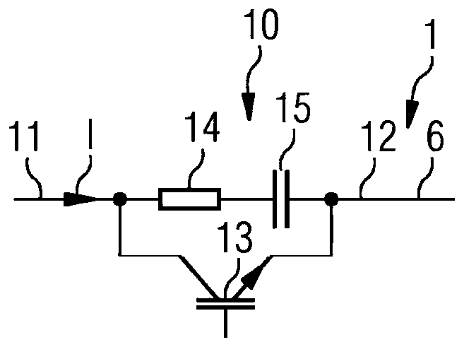
[0038] figure 1 Shown is a schematic structure of a switching module 10 of a switching device 1 according to the invention for separating a current path 6 comprising supply-side and load-side inductances. The switching module 10 comprises a controllable semiconductor switching element 13 . The controllable semiconductor switching element 13 can be an IGBT, a MOSFET, an IGCT or a thyristor with a disconnection device. The load connection of the controllable semiconductor switching element 13 is connected between the first switching module connection 11 and the second switching module connection 12 . A series circuit consisting of a resistor 14 and a capacitor 15 is also arranged between the first and the second switching module connection 11 , 12 . In other words, the RC element formed by the resistor 14 and the capacitor 15 is connected in parallel with the load connection of the controllable switching element 13 .

[0039] The basic mode of operation of such a single switc...


PUM


Abstract

The invention relates to a switching device (1) for disconnecting a current path (6) in a DC supply system, said current path (6) comprising inductors (3, 5) at the source end and the load end. The switching device (1) comprises at least two series-connected switching modules (10), each of which (10) includes at least one controllable semiconductor switching element (13, 16) to which a series circuit consisting of a resistor (14) and a capacitor (15) is connected in parallel.

Description

technical field [0001] The invention relates to a switching device for separating current paths of a direct current network comprising supply-side and load-side inductances. Background technique [0002] A switching device provided for separating the current path of the direct current network including the source-side and load-side inductance must be able to handle the recovery or removal of energy in the direct current network. [0003] In the case of the use of mechanical switches, as in so-called ABB switches, there is a risk of arcing if the separation of the current paths at the zero crossing of the current is not ensured. Such mechanical switching elements must therefore be protected by complex circuits, for example by arranging a plurality of semiconductor switching elements and varistors as overvoltage limiters. For this purpose, for example, a semiconductor switching element which has a low voltage drop during conduction can be connected to a fast-switching mechani...

Claims


Application Information

Patent Timeline
Patent Type & Authority Applications(China)
IPC IPC(8): H03K17/0814H03K17/16
CPCH03K17/08148H03K17/162H03K17/168H03K17/0814H03K17/56
Inventor J.鲁普
Owner SIEMENS ENERGY GLOBAL GMBH CO & KG
Why Eureka
Try Eureka