Thermal imager
a technology of thermal imager and imager, which is applied in the field of thermal imager, can solve the problems of non-incendiary voltage and inability to cause a fir
- Summary
- Abstract
- Description
- Claims
- Application Information
AI Technical Summary
Benefits of technology
Problems solved by technology
Method used
Image
Examples
Embodiment Construction
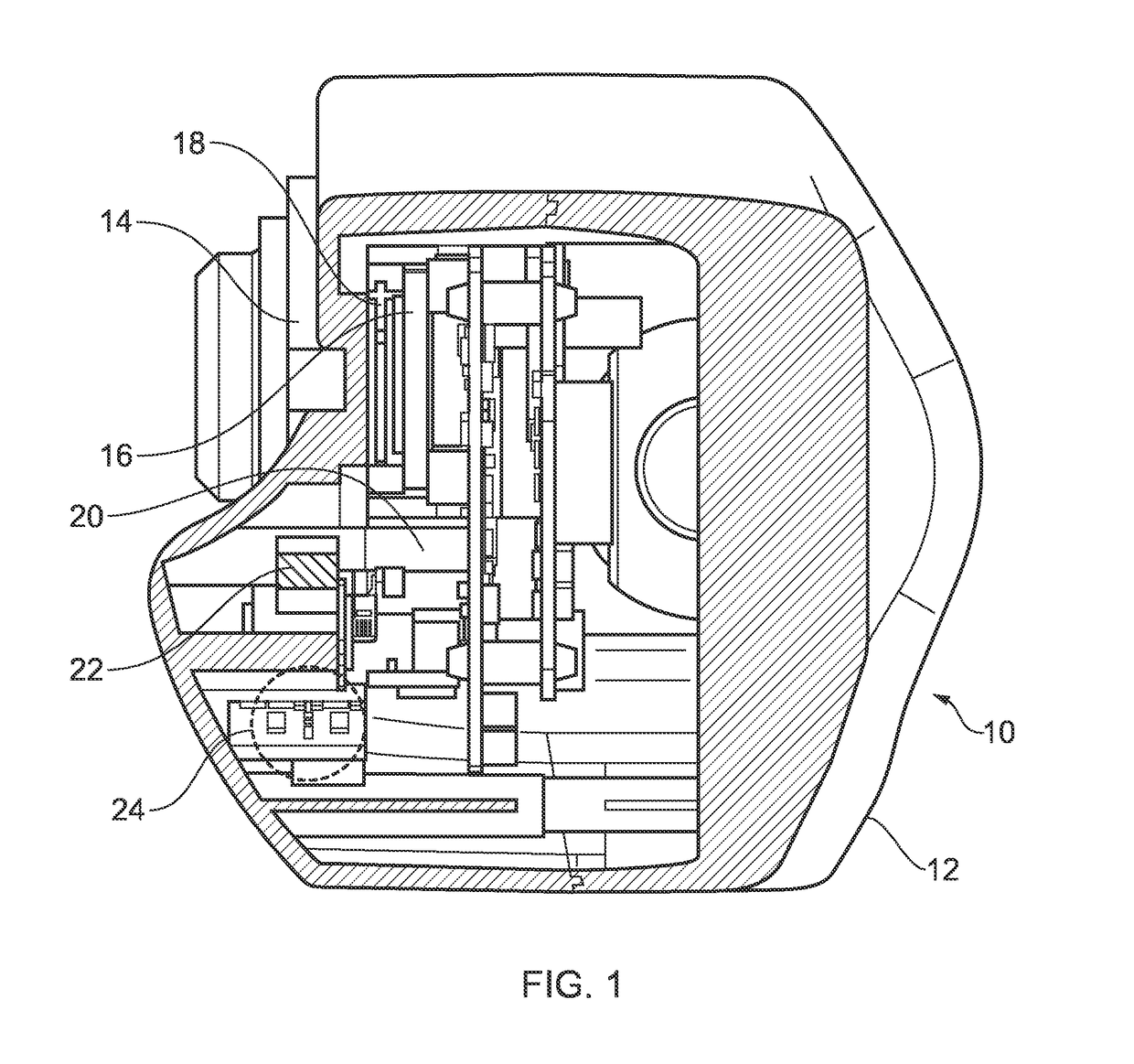
[0058]FIG. 1 shows the thermal imager 10. Inside the casing 12 a detector 16 is positioned in line with the lens 14. Between the lens 14 and the detector 16 and also inside the casing 12, there is a shutter 18. The shutter 18 is attached to a motor 22 by a spindle 20. When the motor 22 operates, it turns the spindle 20 that moves the shutter 18 either between or out from between the lens 14 and the detector 16.
[0059]The shutter 18 may be referred to as a paddle. The shutter 18 is L-shaped, such that the long arm of the L-shaped shutter 18 extends vertically from adjacent to the lens 14 and the detector 16 to the spindle 20, and the short arm of the shutter 18 fills the gap between the lens 14 and the detector 16.
[0060]Components 24 include a battery to store electrical energy, capacitors, diodes, and resistors. The battery is connected to the motor 22. In use, electrical energy from the battery passes through the capacitors, diodes, and resistors to control the capacitance, voltage,...
PUM
 Abstract
Description
Claims
Application Information
 - R&D
- Intellectual Property
- Life Sciences
- Materials
- Tech Scout
- Unparalleled Data Quality
- Higher Quality Content
- 60% Fewer Hallucinations
Browse by: Latest US Patents, China's latest patents, Technical Efficacy Thesaurus, Application Domain, Technology Topic, Popular Technical Reports.
© 2025 PatSnap. All rights reserved.Legal|Privacy policy|Modern Slavery Act Transparency Statement|Sitemap|About US| Contact US: help@patsnap.com


