
Display auxiliary device, display system, display method, and program medium

a technology of display system and auxiliary device, applied in the field of display system, display method, and program medium, can solve problems such as the quality of a projected image to deteriora

Active Publication Date: 2017-04-18
CASIO COMPUTER CO LTD
View PDF18 Cites 0 Cited by
  • Summary
  • Abstract
  • Description
  • Claims
  • Application Information

AI Technical Summary

Benefits of technology

The invention aims to provide a device, system, method, and program for viewing left-eye and right-eye images through viewing glasses without causing black floating for the display device.

Problems solved by technology

Thus, particularly, when a dark image having a small light quantity is projected, a phenomenon called “black floating” that a portion that has to be originally black is projected slightly bright occurs due to influence of a synchronous pulse regardless of a projected image, and it causes the quality of a projected image to deteriorate.

Method used


Image

  • Display auxiliary device, display system, display method, and program medium
  • Display auxiliary device, display system, display method, and program medium
  • Display auxiliary device, display system, display method, and program medium

Examples


Embodiment Construction

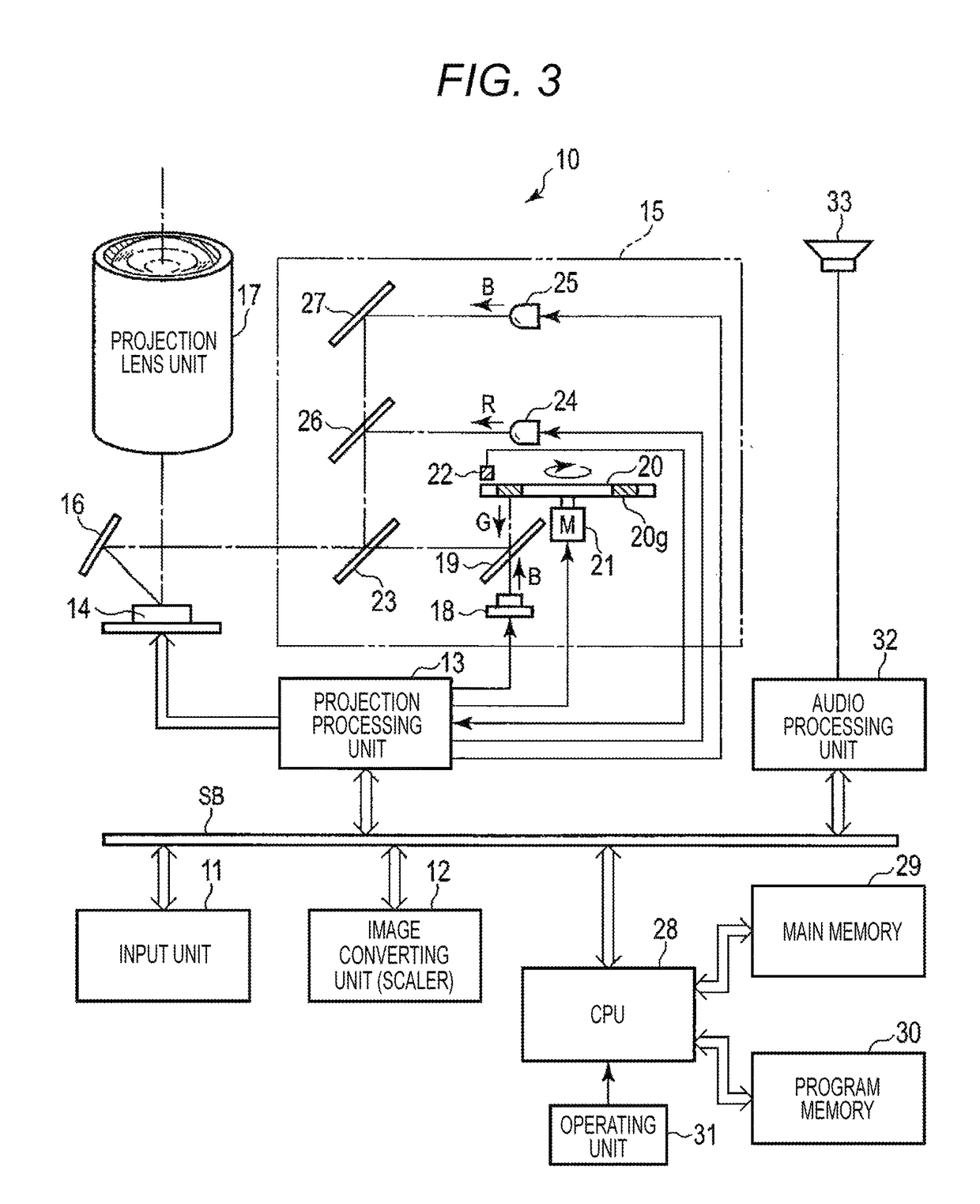
[0021]Hereinafter, an embodiment in which the present invention is applied to a projector device of a DLP (a registered trademark) type will be described with reference to the appended drawings.

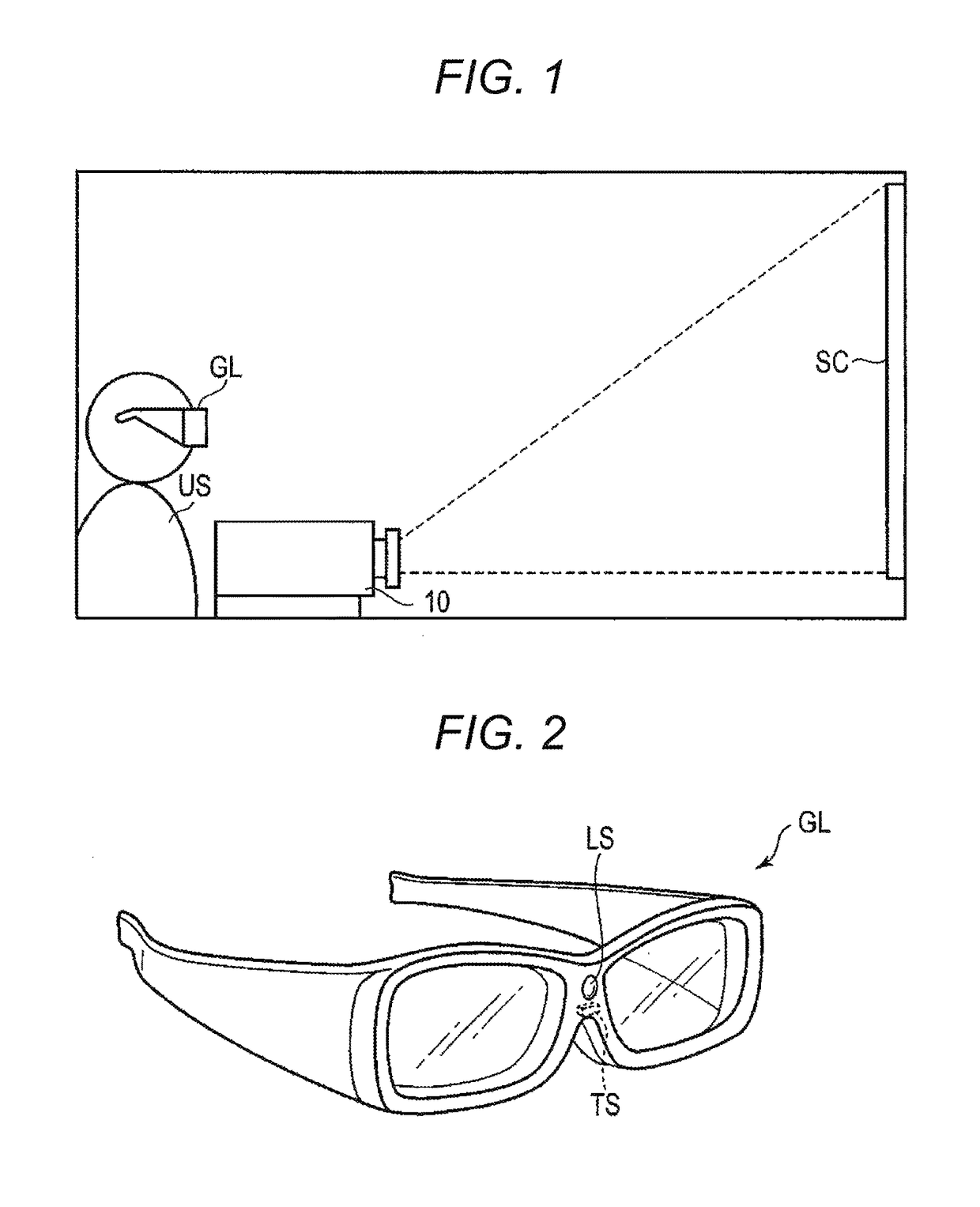
[0022]FIG. 1 is a diagram illustrating an environment of a projection system including a projector device 10 according to the embodiment.

[0023]As illustrated in FIG. 1, a user US wearing 3D liquid crystal glasses GL (viewing glasses or a display auxiliary device) views an image projected onto a screen SC from the projector device 10.

[0024]FIG. 2 is a perspective view illustrating an external configuration of the 3D liquid crystal glasses GL.

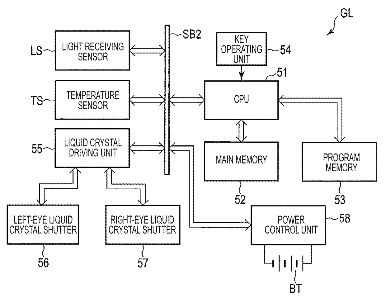
[0025]The 3D liquid crystal glasses GL are over-glasses that can be worn and used even by the user US being wearing glasses, and a light receiving sensor LS is arranged at a front side of a bridge portion at the center thereof.

[0026]The light receiving sensor LS detects a change in illuminance of the screen SC plane when it faces the screen SC.

[0027]As lef...


PUM


Abstract

A display auxiliary device includes a light receiving sensor that receives display light from a display target, and a CPU that determines whether or not a switching display synchronous signal is included in the received display light, shields both a left-eye liquid crystal shutter and a right-eye liquid crystal shutter during a light reception period of time of the switching display synchronous signal based on the switching display synchronous signal, and performs a shutter switching operation of the left-eye liquid crystal shutter for the left-eye image and the right-eye liquid crystal shutter for the right-eye image to be switched and displayed, when the switching display synchronous signal is determined to be included.

Description

BACKGROUND[0001]1. Technical Field[0002]The present invention relates, particularly, to a display auxiliary device, a display system, a display method, and a program medium that are suitable for a projector of a digital light processing (“DLP (a registered trademark)”) type or the like.[0003]2. Related Art[0004]A technique of visualizing a three-dimensional (3D) (stereoscopic) image by projecting the 3D image together with a synchronous pulse in a projector of a DLP (a registered trademark) type has been known (for example, JP 2011-070193 A).[0005]The projector of the DLP type including the technique disclosed in JP 2011-070193 A employs a configuration in which when projection of a 3D image is performed while switching a left-eye image and a right-eye image, a projector side emits a synchronous pulse having high brightness during a very short period of time regardless of an original image signal, and a 3D glasses (viewing glasses) side controls synchronization between the left-eye ...

Claims


Application Information

Patent Timeline
Patent Type & Authority Patents(United States)
IPC IPC(8): G09G3/00G09G3/36H04N13/04H04N13/363
CPCG09G3/3648H04N13/0422H04N13/0427H04N13/0438H04N13/0459H04N2213/008G03B35/16H04N13/363H04N13/398H04N13/365H04N13/324H04N13/341
Inventor ODA, KIYOSHIYOSHINO, KEN
Owner CASIO COMPUTER CO LTD
Learn More