Display device

a display device and display technology, applied in the field of display devices, can solve the problems of reducing resolution, and achieve the effects of reducing the variation of display among the plurality of pixels, and prolonging the li

Inactive Publication Date: 2015-03-24
SEMICON ENERGY LAB CO LTD
View PDF34 Cites 0 Cited by
  • Summary
  • Abstract
  • Description
  • Claims
  • Application Information

AI Technical Summary

Benefits of technology

[0015]In a display device according to one embodiment of the present invention, a plurality of pixels which perform desired color display are changed depending on the display state. Thus, as compared to the case where a plurality of pixels which perform desired color display are fixed when 3D display is performed, the display device can have a longer period until display change (display deterioration) in a pixel becomes obvious (a longer lifetime) and variations in display among the plurality of pixels can be reduced. Specifically, in the case where a plurality of pixels which perform desired color display are fixed when 3D display is performed, there is a possibility that a period during which part of the plurality of pixels perform desired color display is extremely longer than a period during which the other part of the plurality of pixels perform desired color display. In addition, only display performed by the part of the plurality of pixels may be significantly changed from the initial display. In this case, by changing the plurality of pixels which perform desired color display depending on the display state, the display device can have a longer period until display change in the pixel becomes obvious (a longer lifetime) and variations in display among the plurality of pixels can be reduced.

Problems solved by technology

However, in the case where a display device performing 3D display by an autostereoscopic system performs 2D display, the resolution is decreased due to a unique structure (e.g., a parallax barrier) of an autostereoscopic system.

Method used


Image

  • Display device
  • Display device
  • Display device

Examples


embodiment 1

[0030]In this embodiment, a display device according to one embodiment of the present invention will be described with reference to FIGS. 1A to 1C, FIG. 2, FIG. 3, and FIG. 4.

Structure Example of Display Device

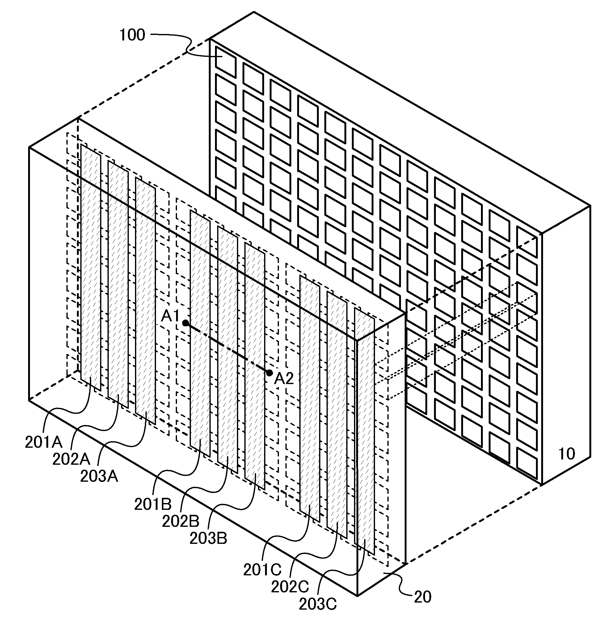
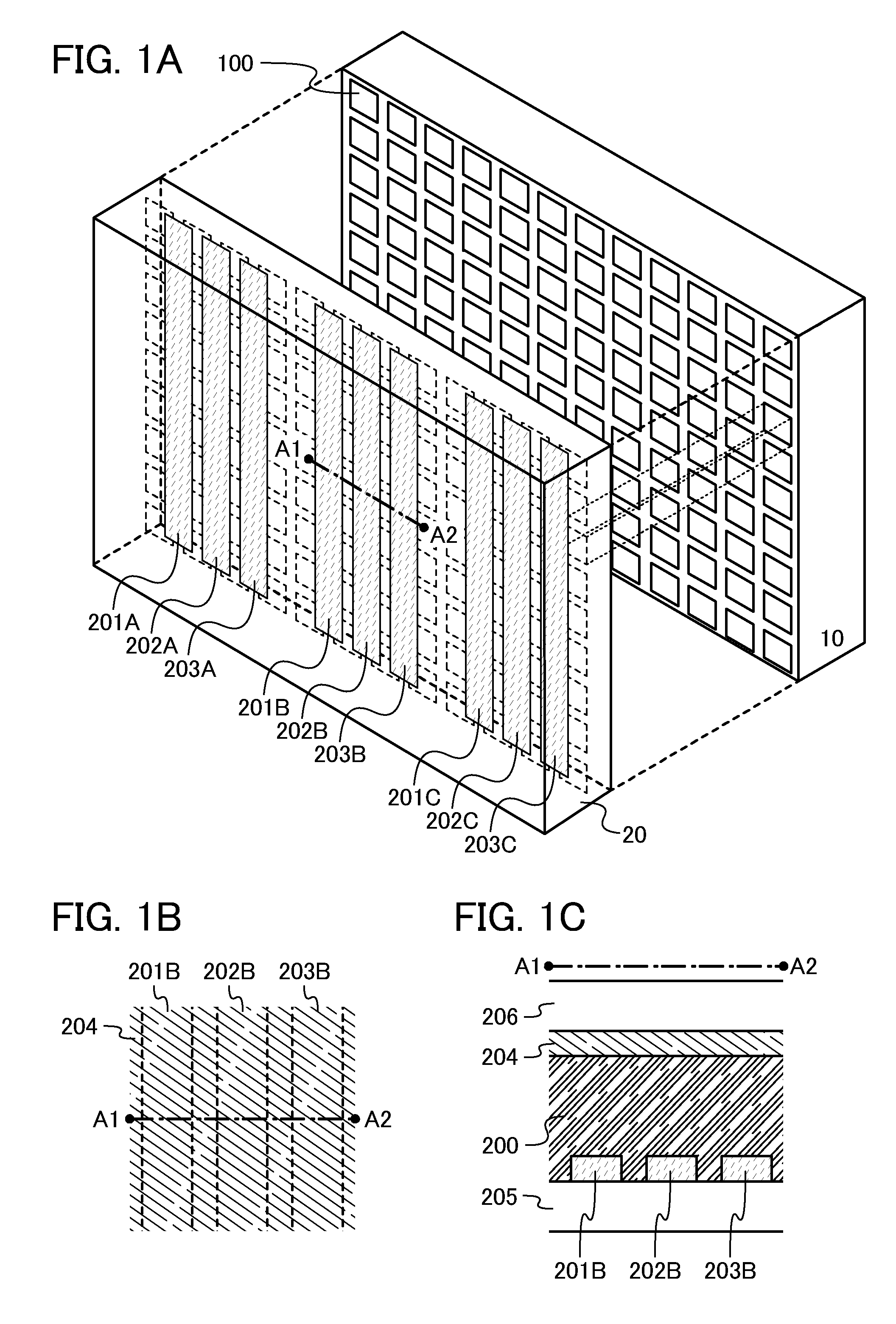
[0031]FIG. 1A illustrates a structure example of the display device in this embodiment. The display device in FIG. 1A includes a display panel 10 and a shutter panel 20. The display panel 10 includes a plurality of pixels 100 which are provided in matrix. Display is performed using the plurality of pixels 100. The shutter panel 20 includes electrodes 201A to 201C, 202A to 202C, and 203A to 203C which are provided in parallel or substantially parallel to one another (in stripes). Note that the electrodes 201A to 201C, 202A to 202C, and 203A to 203C transmit light.

[0032]Note that in the display device in FIG. 1A, the width of each of the electrodes 201A to 201C, 202A to 202C, and 203A to 203C is the same or substantially the same as the width of the pixel 100. Further, there is ...

modification example

[0048]The above display device is one embodiment of the present invention; the present invention also includes a display device that is different from the above display device.

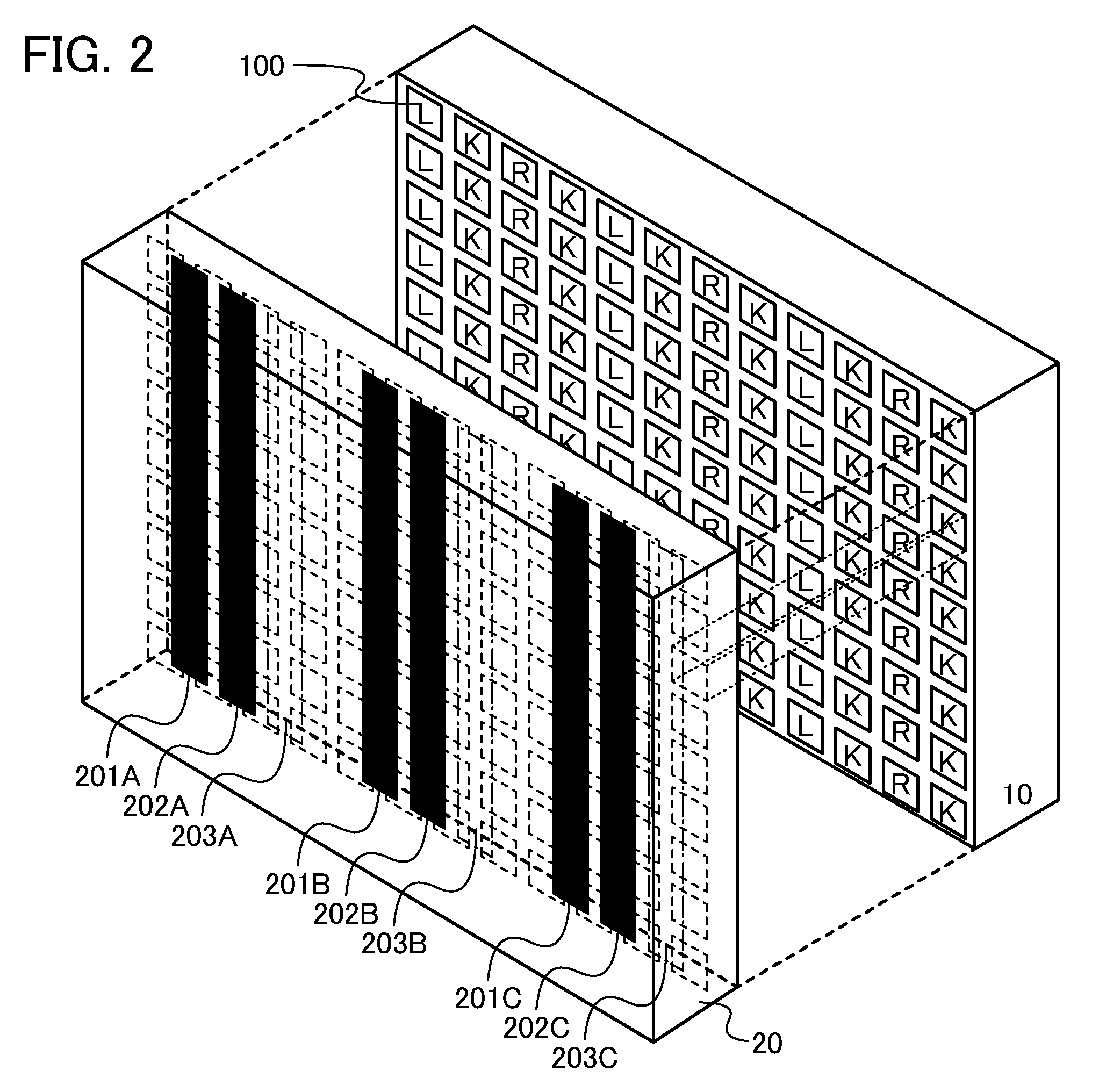
[0049]For example, the electrodes 202A to 202C in FIG. 1A can be replaced with light-blocking layers 210A to 210C (see FIG. 5). Note that the light-blocking layers 210A to 210C do not mean layers which select a light-transmitting state or a light-blocking state depending on an input signal but mean layers always having a light-blocking property. The display device in FIG. 5 can be brought into the display state in FIG. 2 and the display state in FIG. 3. Thus, in the display device in FIG. 5, the occurrence of crosstalk can be suppressed and variations in display among the plurality of pixels can be reduced. The display device in FIG. 5 can have a longer period until display change in the pixel 100 becomes obvious (a longer lifetime).

[0050]The shutter panel 20 in FIG. 1A can have a structure in which an electro...

embodiment 2

[0051]In this embodiment, a display device according to one embodiment of the present invention, which is different from Embodiment 1, will be described with reference to FIGS. 7A to 7C, FIG. 8, FIG. 9, FIG. 10, and FIG. 11.

Structure Example of Display Device

[0052]FIG. 7A illustrates a structure example of the display device in this embodiment. The display device in FIG. 7A includes a display panel 10 and a shutter panel 30. Further, the shutter panel 30 includes electrodes 301A to 301C, 302A to 302C, 303A to 303C, 304A, and 304B which are provided in parallel or substantially parallel to one another, and electrodes 321A, 321B, 322A, 322B, 323A, 323B, 324A, and 324B which are provided in parallel or substantially parallel to one another. Note that the electrodes 301A to 301C, 302A to 302C, 303A to 303C, 304A, and 304B are perpendicular or substantially perpendicular to the electrodes 321A, 321B, 322A, 322B, 323A, 323B, 324A, and 324B. In addition, the electrodes 301A to 301C, 302A t...


PUM


Abstract

The occurrence of crosstalk in a display device which performs 3D display is suppressed. When 3D display is performed, part of a plurality of pixels perform desired color display and the other part of the plurality of pixels perform black display. Thus, as compared to the case where all of a plurality of pixels perform desired color display, the occurrence of crosstalk can be suppressed. A plurality of pixels which perform desired color display are changed depending on the display state. Therefore, as compared to the case where a plurality of pixels which perform desired color display are fixed when 3D display is performed, the display device can have a longer period until display change in a pixel becomes obvious (a longer lifetime) and variations in display among the plurality of pixels can be reduced.

Description

BACKGROUND OF THE INVENTION[0001]1. Field of the Invention[0002]The present invention relates to a display device. In particular, the present invention relates to a display device capable of performing 3D display.[0003]2. Description of the Related Art[0004]Display devices are widely used, ranging from large display devices such as television devices to small display devices such as mobile phones. The display devices each include a display portion in which a plurality of pixels are provided in matrix. Desired color display is performed in each pixel, so that an image is formed in the display portion. In recent years, display devices capable of performing 3D display have been developed.[0005]As systems for performing 3D display, there are a system (a glasses system) in which a period of display for a left eye and a period of display for a right eye are distinguished from each other in a display portion and a user wears glasses so that the left eye sees the former display and the righ...

Claims


Application Information

Patent Timeline
Patent Type & Authority Patents(United States)
IPC IPC(8): G09G5/00G09G3/00H04N13/04
CPCG09G3/003H04N13/0413H04N13/0422H04N13/0452H04N13/31H04N13/315H04N13/324H04N13/356G02F1/13G02B30/00G09G3/3208G09G2320/0209G09G2320/10
Inventor MIYAKE, HIROYUKI
Owner SEMICON ENERGY LAB CO LTD
Why Eureka
Try Eureka