

Clamp and pivoting flag for tables
a technology for pivoting flags and tables, applied in mechanical visible signalling, advertising, identification means, etc., can solve the problems of time-consuming and/or frustrating signaling techniques, high cost, and inconvenience for other patrons, and achieve the effect of easy traction
- Summary
- Abstract
- Description
- Claims
- Application Information
AI Technical Summary
Benefits of technology
Problems solved by technology
Method used
Image

Examples
first embodiment
[0112]FIGS. 1-17 cover the novel clamp with pivoting arm / flag with a clamping thickness of approximately 1½″ to approximately 2¼″ using a hidden pin connection.
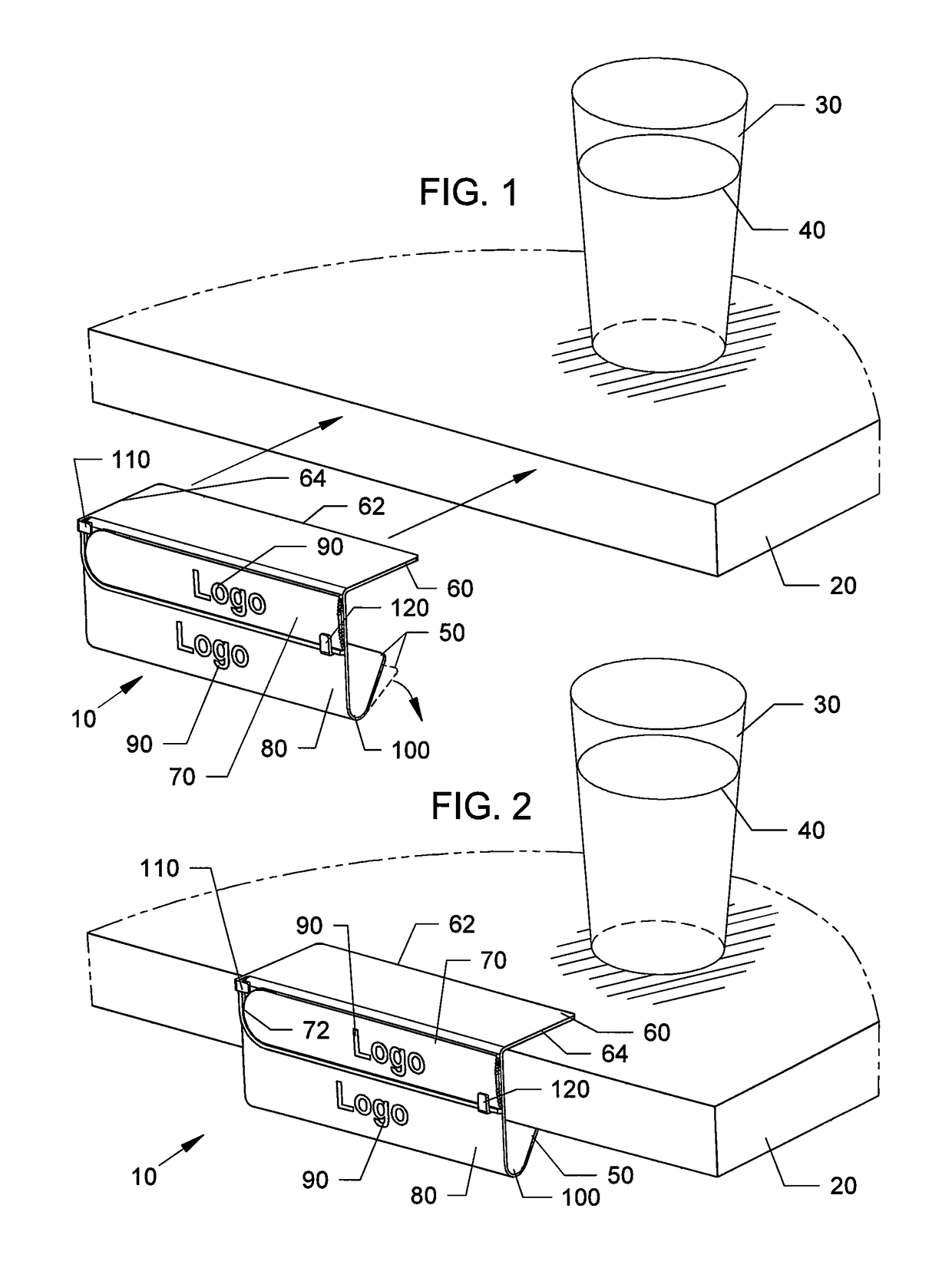
[0113]FIG. 1 is a perspective exploded view of the novel clamp with pivoting arm / flag assembly 10 in position to clip onto an edge of a table 20. FIG. 2 is another perspective view of the clamp with pivoting arm / flag assembly 10 clipped onto the edge of the table 20.
[0114]Referring to FIGS. 1-2, assembly 10 can be used with tables having a thickness of approximately 1.5″ to approximately 2.25″. The assembly 10 can include a top generally rigid flat planar clamp leg 60 and a lower generally flexible clamp leg 50 that can have a tip edge which can abut against a bottom of the table top. The top generally rigid flat planar leg 60 can generally be flush against a top surface of the table 20. Here, the glass 30 is shown full of liquid 40 so no service from a waitress or other wait staff is required so the arm / flag 70 is in a down(...
second embodiment
[0127]FIGS. 18-25 cover the novel clamp with pivoting arm / flag having a clamping thickness of approximately ⅞″ to approximately 1½″ with a hidden pin connection.
[0128]FIG. 18 is a top perspective view of another embodiment of the clamp with pivoting arm / flag assembly 180 clipped to an edge of a smaller thickness tables 200 (approximately ⅞″ to 1.5″ thick). Similar to FIG. 1, the serving glass 30 is shown full so no service is required so the server flag 70 is down relative to back panel 190.
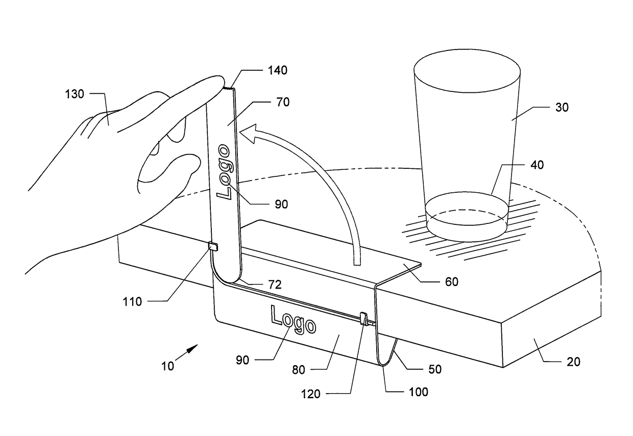
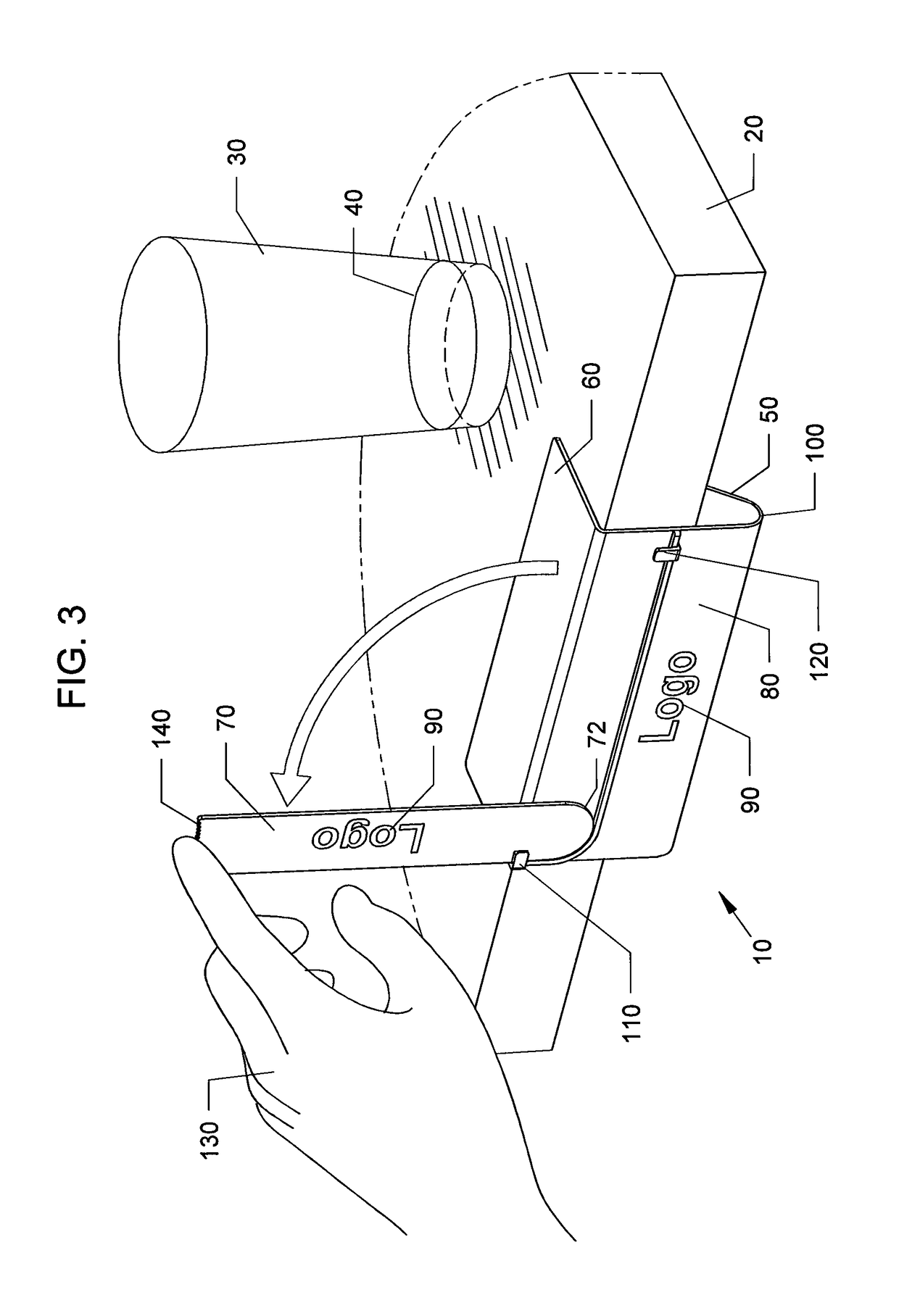
[0129]FIG. 19 is another perspective view of the clamp with pivoting arm / flag assembly 180 clipped to the edge of the table 200 of FIG. 18 with the arm / flag 70 being raised by patron's finger on their hand 130. Here, the serving glass 30 is near empty. The patron can use a finger from their hand 130 placed on the grip knurl 140 of the arm / flag 70 to raise the arm / flag 70 thereby alerting the server that service is desired.
[0130]FIG. 20 is a front view of the clamp with pivoting arm / flag assembly ...
third embodiment
[0132]FIGS. 26-37 cover the novel clamp with pivoting arm / flag having a clamping range of approximately ½″ to approximately 2″ with a more efficient pin connection.
[0133]FIG. 26 is a top perspective view of the clamp with pivoting arm / flag assembly 220 similar to the preceding figures clipped to an outer edge of a table 200 with arm / flag 70 in the down position. Here, a sales receipt 240 and / or a credit card 230 are shown inserted between the front of back panel 260 and the lowered arm / flag 70.
[0134]FIG. 27 is another view of the clamp with pivoting arm / flag assembly 220 of FIG. 26 with arm / flag 70 raised to an up open position to rest against clip 270 which can function as a stop to limit travel of the arm / flag 70 to a generally upright vertical position.
[0135]FIG. 28 is a front view of the clamp with pivoting arm / flag assembly 220 with a pivoting pin locking plug 250 attaching the arm / flag 70 to the back panel 260 of the assembly 220. FIG. 29 is a rear view of the clamp with pivot...
PUM
 Abstract
Description
Claims
Application Information