Depth sensing using optical pulses and fixed coded aperature

a depth sensing and optical pulse technology, applied in the field of reconstruction of scenes using optical pulses, can solve the problems of high frame rate, complex and expensive sensors, and expensive arrays of precision tof sensors, so as to reduce the number of required sensors, enhance the capabilities of depth sensing systems, and reduce the cost

Active Publication Date: 2017-05-02
MITSUBISHI ELECTRIC RES LAB INC
View PDF9 Cites 17 Cited by
  • Summary
  • Abstract
  • Description
  • Claims
  • Application Information

AI Technical Summary

Benefits of technology

[0019]Continuous improvement in optical sensing components, as well as recent advances in signal acquisition theory, provide an opportunity to reduce the cost and enhance the capabilities of depth sensing systems. The embodiments of the invention provide a novel depth sensing system and method that uses a fixed coded aperture (mask) to significantly reduce the number of required sensors, compared to conventional systems. As an advantage, the mask can be cheaply printed on any transparent substrate.
[0020]The embodiments also provide a modeling and reconstruction framework based on model-based compressed sensing, which characterizes a large variety of depth sensing systems. Experimental data indicate that it is possible to reduce the number of sensors by more than 85% with a negligible effect on the sensing quality.
[0024]a model-based compressive sensing (CS) reconstruction method that exploits a low variation (TV) of depth scenes to improve the reconstruction.
[0025]In contrast with the prior art, the embodiments use a small number of sensors and a fixed coded aperture. The aperture is a very inexpensive component compared to a spatial light modulator (SLM). Because the code does not change, one embodiment of the invention only requires a single pulse transmission per frame—that is a depth map in a sequence of depth maps—which may or may not carry a code. Thus, frame-rates equivalent to much more expensive single-pulse systems can be achieved at a significantly lower cost.

Problems solved by technology

However, the gains are significant for imaging systems that depend on complex costly sensors, such as “time-of-flight” (TOF) light or radar sensors.
Conventional high-resolution, high frame-rate optical based systems typically use an expensive array of precision TOF sensors and illuminate the scene with singular pulses transmitted by a stationary laser.
The resulting system significantly lowers the cost, but requires the use of mechanical components, which can be prone to failure and cumbersome in mobile applications.
However, that restricts those system to static scenes, see Howland et al.,“Compressive Sensing Lidar for 3D imaging,” CLEO: Science and Innovations.
In addition, spatial light modulators (SLM) are relative expensive, e.g., $1000 or more depending on the desired resolution, see Holoeye® or Texas Instruments DLP® products.

Method used


Image

  • Depth sensing using optical pulses and fixed coded aperature
  • Depth sensing using optical pulses and fixed coded aperature
  • Depth sensing using optical pulses and fixed coded aperature

Examples


Embodiment Construction

[0031]The embodiments of our invention provide a method and system for reconstructing a scene using optical sensing and a fixed coded aperature.

[0032]Optical Sensing

[0033]System Architecture

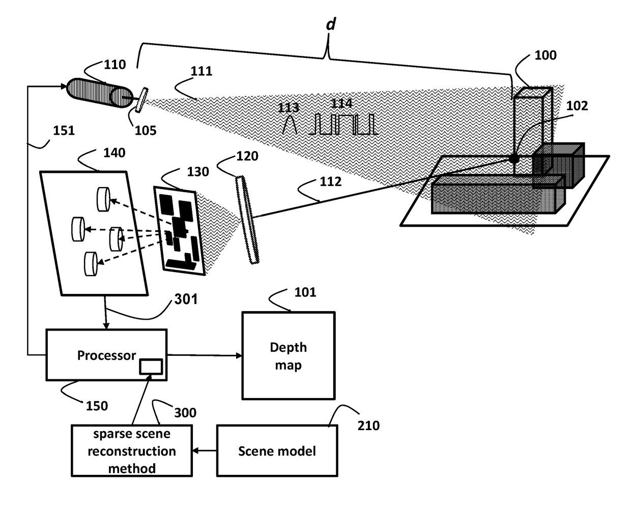
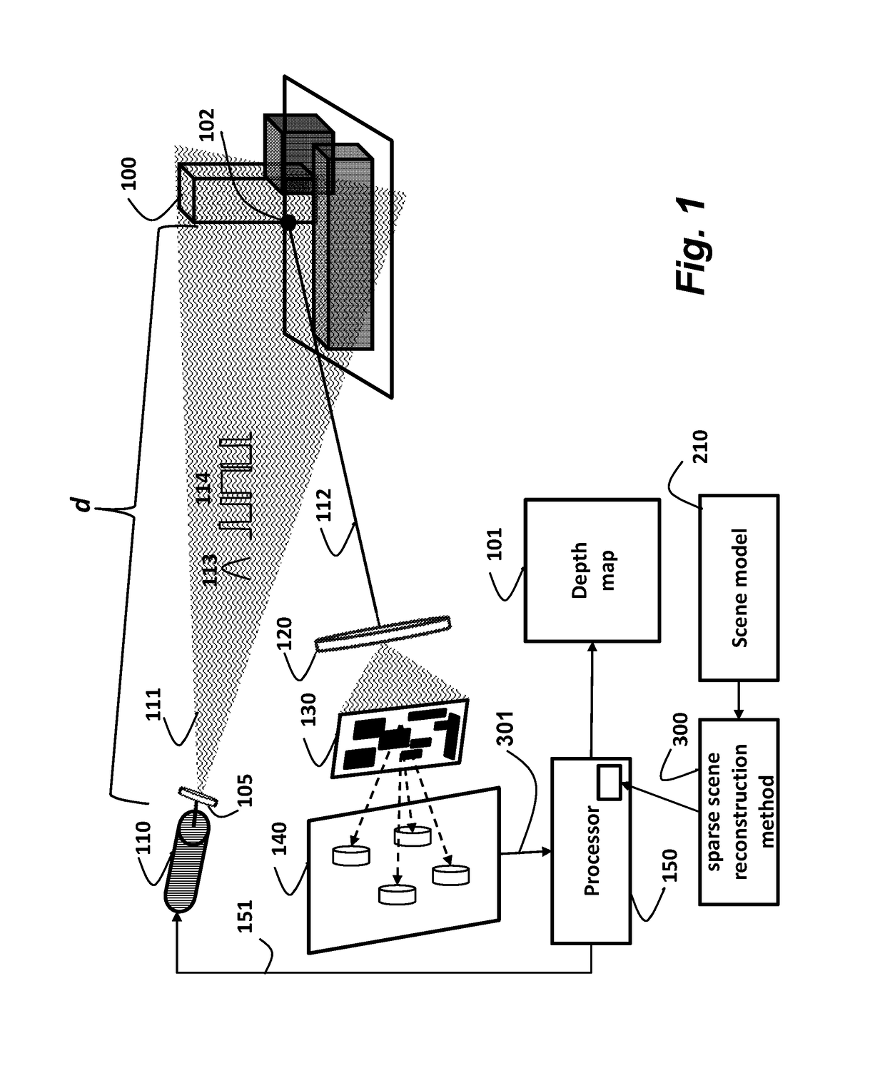
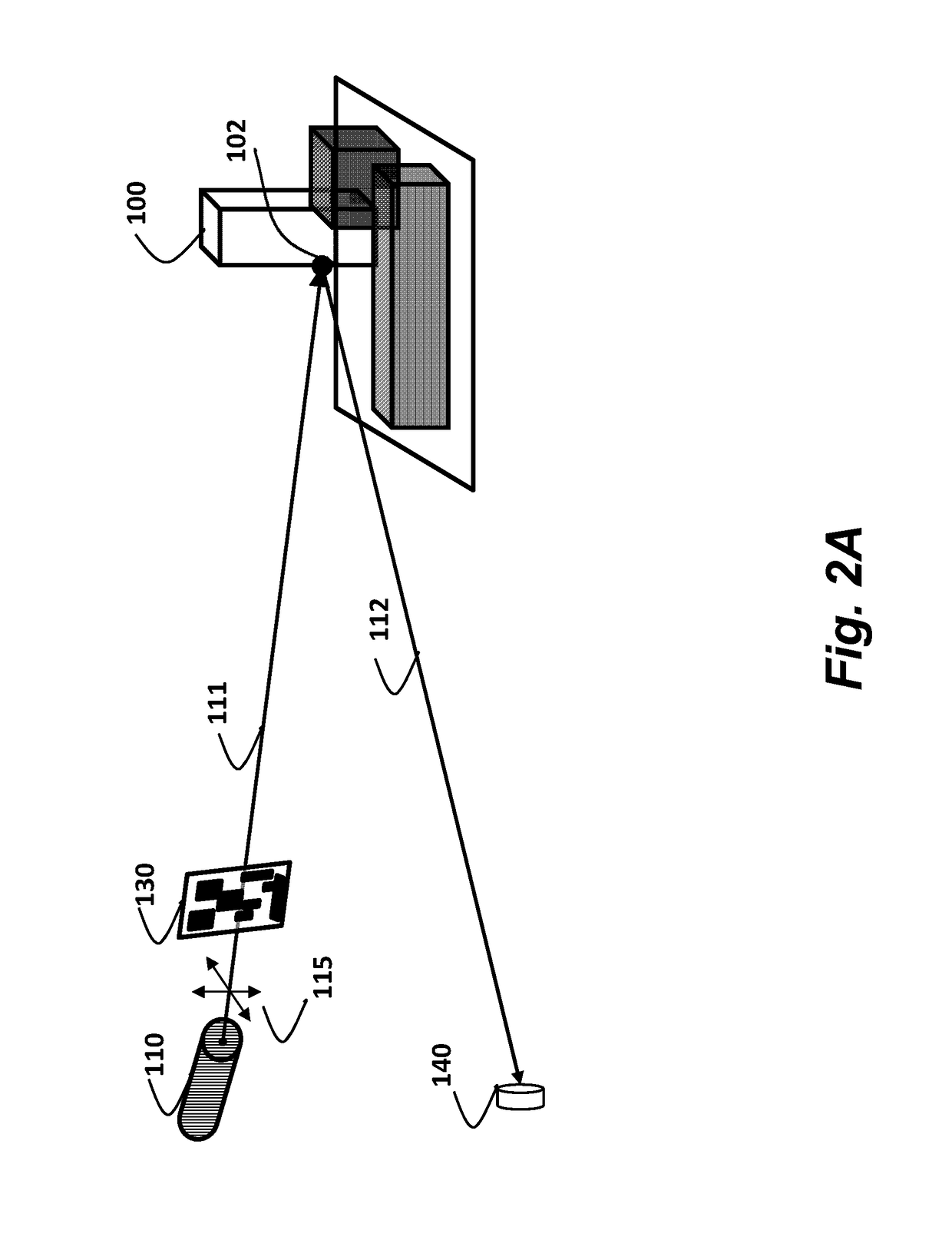
[0034]As shown in FIG. 1, a stationary light source 110, e.g., a laser, transmits an optical pulse for each frame to be acquired of a scene 100. A lens turns the pulse into a wide beam pulse 111. By using a wide beam pulse, the scene does not need to be scanned. The pulse can be, for example, Gaussian shaped 113 in time. Alternatively, a coded sequence of pulses 114 can be used.

[0035]A reflected pulse 112, from each scene point 102 that is a reflector, passes through a lens 120, which disperses the reflected pulse to a set of sensors 140 arranged in a plane with the light source. This way the total distance is simply 2d. The dispersed pulse passes through a fixed code aperture 130 in the form of a mask in an optical path between the light source and the scene. The mask can be cheaply printed on a...


PUM


Abstract

In a system and method for reconstructing a scene, a light source transmits an optical pulse unto the scene, and a set of sensors receive a reflected pulse to acquire sensed signals corresponding to the optical pulse. There is a fixed coded aperture in an optical path between the light source and set of sensors. Then, a processor performs a method to reconstruct the scene as a three-dimensional (3D) depth map using a scene model.

Description

RELATED APPLICATION[0001]This Application is a related to U.S. patent application Ser. No. 13 / 405,504, “Depth Sensing Using Active Coherent Signals,” filed by Boufounos on Feb. 27, 2012, and incorporated herein by reference. That Application provides a method for sensing depths in a scene using active coherent sensing of reflected radar pulses using a single transmitter and multiple receivers arranged in a plane, using back projection.FIELD OF THE INVENTION[0002]This invention relates generally to reconstructing a scene using optical pulses, and more particularly to reconstructing the scene as a three dimensional (3D) depth map.BACKGROUND OF THE INVENTION[0003]Compressive Sensing[0004]Compressive Sensing (CS) uses fewer linear measurements than implied by the dimensionality of an acquired signal. To reduce the acquisition rate, CS reconstruction methods exploit the structure of signals. To capture the structure, the most commonly used signal model is sparsity.[0005]As used herein, s...

Claims


Application Information

Patent Timeline
Patent Type & Authority Patents(United States)
IPC IPC(8): G01C11/12G01S17/89G01S7/486G01S17/10G01S7/4865
CPCG01S17/89G01S7/4865G01S17/10
Inventor BOUFOUNOS, PETROS T.KADAMBI, ACHUTA
Owner MITSUBISHI ELECTRIC RES LAB INC
Why Eureka
Try Eureka