Mounting and component holder apparatuses and assemblies for holding rigid components

a technology for mounting components and components, which is applied in the field of mounting components and component holders apparatuses and assemblies for holding rigid components, and can solve the problems of time-consuming and costly fabrication of enclosures, inability to visually discern the orientation of metallic racks on enclosures, and often metallic enclosures

Active Publication Date: 2017-05-09
EVOLUTION ENG
View PDF10 Cites 16 Cited by
  • Summary
  • Abstract
  • Description
  • Claims
  • Application Information

AI Technical Summary

Problems solved by technology

Because of the extensive milling that may be required to modify and mount the enclosures, they often need to be made of strong materials and thus the enclosures are often metallic.
In addition, the fabrication of such enclosures can be time consuming and costly.
Because of the way the enclosures are customized, the orientation of the metallic racks on the enclosures may not be visually discernible.

Method used


Image

  • Mounting and component holder apparatuses and assemblies for holding rigid components
  • Mounting and component holder apparatuses and assemblies for holding rigid components
  • Mounting and component holder apparatuses and assemblies for holding rigid components

Examples


first embodiment

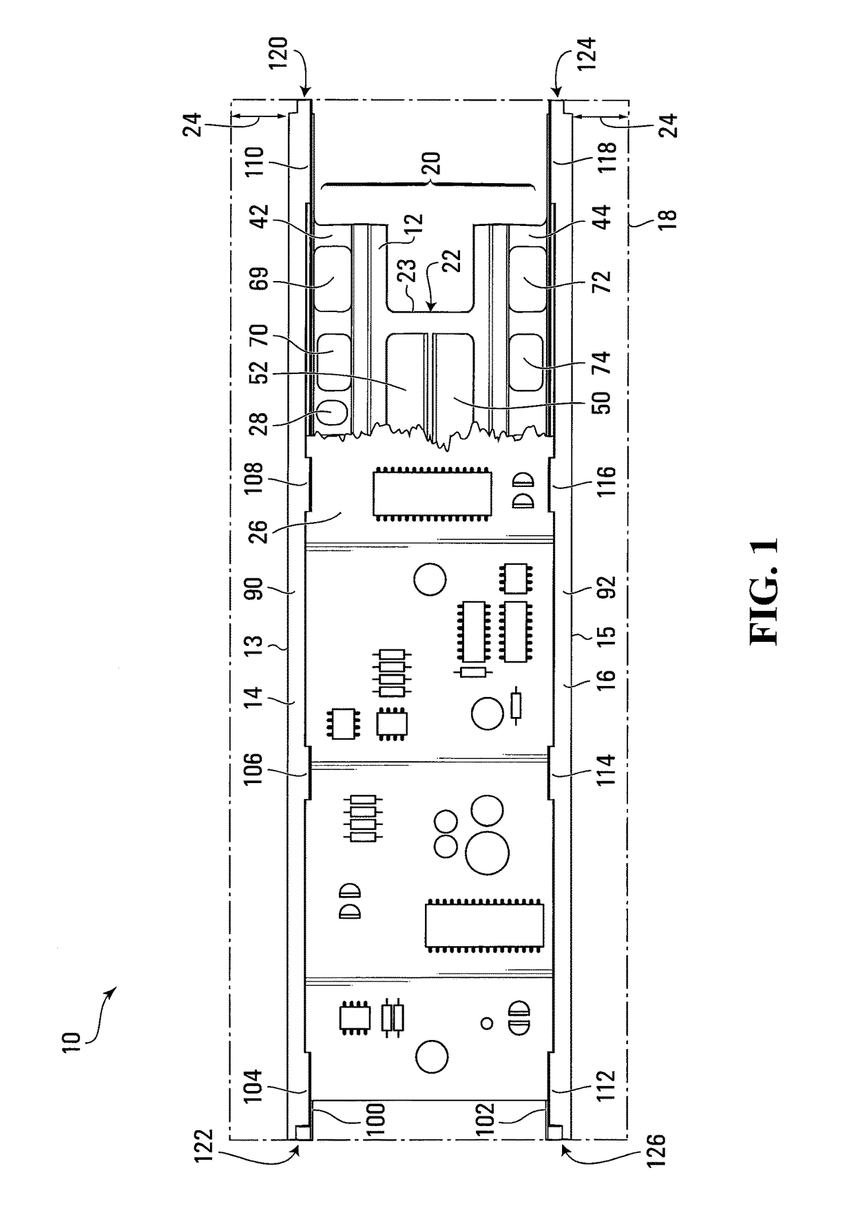
[0155]Referring to FIG. 1, a component mounting apparatus for holding a rigid component in a downhole bore or downhole collar based application according to the invention is shown generally at 10. The apparatus includes a first body 12 having first and second component mounts 13 and 15 and a first support shown generally at 20 connecting the component mounts together. In the embodiment shown, the first and second component mounts 13 and 15 include first and second parallel spaced apart component holders 14 and 16 disposed in and defining a first common plane or mounting plane 18. However in another embodiment, such as the embodiment shown in FIGS. 15 and 16, first and second component mounts may include first and second standoffs.

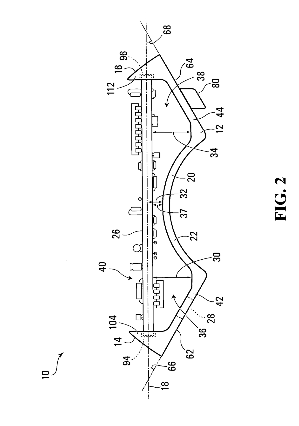
[0156]Referring to FIG. 2, the first support 20 includes first and second connecting interfaces 42 and 44 and a connecting portion 22, which connects the first and second connecting interfaces 42 and 44 together. The connecting portion 22 extends between th...

second embodiment

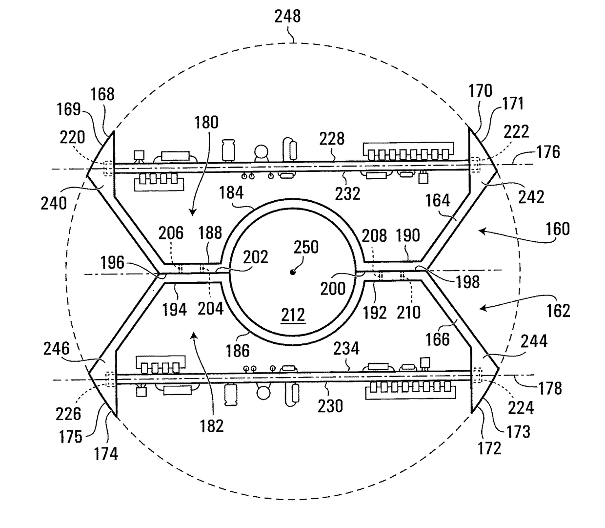
[0175]Referring to FIG. 7, third and fourth mounting apparatuses 160 and 162 are shown. The third and fourth apparatuses 160 and 162 are similar to but not identical to the apparatus 10 shown in FIGS. 1 through 4 and are connected together in a back to back relationship. In this embodiment, the first and second apparatuses are comprised of first and second bodies 164 and 166, respectively, each having first and second component mounts 169, 171 and 173, 175. In the embodiment shown, the first and second component mounts 169, 171 and 173, 175 include first and second parallel spaced apart component holders 168, 170 and 172, 174 respectively disposed in or defining respective common planes 176, 178 and connected together by respective supports 180, 182 having respective connecting portions 184, 186 respectively. The connecting portions 184, 186 may be resilient but need not be.

[0176]Each of the supports 180, 182 also has first and second connecting interfaces 188, 190 and 192, 194 hav...

third embodiment

[0181]Referring to FIG. 8, a first-level component holder assembly employing mounting apparatuses is shown generally at 529. The assembly 529 includes fifth and sixth mounting apparatuses 530 and 532, connected together. In this embodiment, the fifth and sixth apparatuses 530 and 532 are similar to but not identical to the third and fourth apparatuses 160 and 162 described above in connection with FIG. 7. The fifth and sixth apparatuses 530 and 532 are comprised of first and second bodies 534 and 536, respectively, each having first and second component mounts 537, 539 and 541, 543. In the embodiment shown, the first and second component mounts 537, 539 and 541, 543 include first and second parallel spaced apart component holders 538, 540 and 542, 544 respectively, disposed in respective common planes 546, 548 and connected together by respective supports 550, 552 having respective connecting portions 554, 556 respectively. Each of the supports 550, 552 also has first and second co...


PUM


Abstract

A component mounting apparatus for holding a rigid component in a downhole bore or a downhole collar based application includes a first body including first and second parallel spaced apart component holders disposed in a first common plane and a first support connecting the component holders together. The first and second parallel spaced apart component holders are operable to receive and grip a rigid component between the first and second parallel spaced apart component holders. Various component mounting assemblies and configurations may be realized using the component mounting apparatus described. The component mounting apparatus and various mounting assemblies may be used to mount a printed circuit board in a cylindrical enclosure or tubular housing, for example.

Description

BACKGROUND OF THE INVENTION[0001]1. Field of Invention[0002]This invention relates to mounting and component holder apparatuses and assemblies for holding rigid components in downhole bore or downhole collar based applications. It may be particularly advantageous to hold a circuit board for example, in a downhole bore or downhole collar assembly, and more particularly in a measurement while drilling or logging while drilling component thereof.[0003]2. Description of Related Art[0004]It is often necessary to hold a rigid component in a mounting or component holder apparatus or assembly such that the component is prevented from moving. This is particularly true in downhole bore assemblies where it may be necessary to mount the rigid component on an enclosure in the downhole bore assembly.[0005]Conventional technologies for holding rigid components in a downhole bore assembly may involve extensive modification and / or milling of an enclosure to allow for the mounting of circuit boards, ...

Claims


Application Information

Patent Timeline
Patent Type & Authority Patents(United States)
IPC IPC(8): E21B47/01
CPCE21B47/01
Inventor LOGAN, AARON W.LIU, JILI JERRYSWITZER, DAVID ALOGAN, JUSTIN C.
Owner EVOLUTION ENG
Why Eureka
Try Eureka