Portable electronic device

a keyboard device and electronic technology, applied in the field of portable electronic devices, can solve the problems of limited outer appearance of the keyboard device, protruding pillar of the keyboard device protruding from the hinge base, and easy damage of the protruding pillar, so as to achieve the effect of not being easily damaged by an external for

Active Publication Date: 2017-05-09
INVENTEC PUDONG TECH CORPOARTION +1
View PDF3 Cites 15 Cited by
  • Summary
  • Abstract
  • Description
  • Claims
  • Application Information

AI Technical Summary

Benefits of technology

[0019]As a result, the tablet computer may receive a force to rotate the hinge base through the rotating element, thereby adjusting the inclination of the tablet computer. In addition, when the tablet computer is separated from the expansion assembly, the rotating element may slide out along the oblique wall of the second concave portion and return to the first concave portion due to the magnetic force of the first magnet. Therefore, it is helpful to the outer appearance of the expansion assembly, and the rotating element is not easily damaged by an external force because the rotating element is located in the hinge base and does not protrude outward too much.

Problems solved by technology

However, after the tablet computer is separated from the keyboard device, the protruding pillar of the keyboard device protrudes from the hinge base too much, such as in a range from about 6 mm to 8 mm.
As a result, not only is the outer appearance of the keyboard device limited, but also the protruding pillar may easily be damaged by an external force since the protruding pillar protrudes outward too much.
In addition, if the height of the protruding pillar of the keyboard device is reduced, the protruding pillar on the hinge base may easily be separated from the recess of the tablet computer when the tablet computer is rotated on the hinge base of the keyboard device, which is an inconvenient factor for users.

Method used


Image

  • Portable electronic device
  • Portable electronic device
  • Portable electronic device

Examples


Embodiment Construction

[0028]Reference will now be made in detail to the present embodiments of the invention, examples of which are illustrated in the accompanying drawings. Wherever possible, the same reference numbers are used in the drawings and the description to refer to the same or like parts.

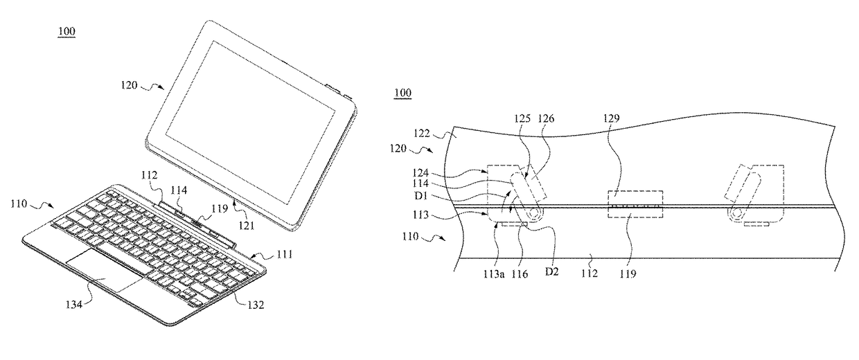
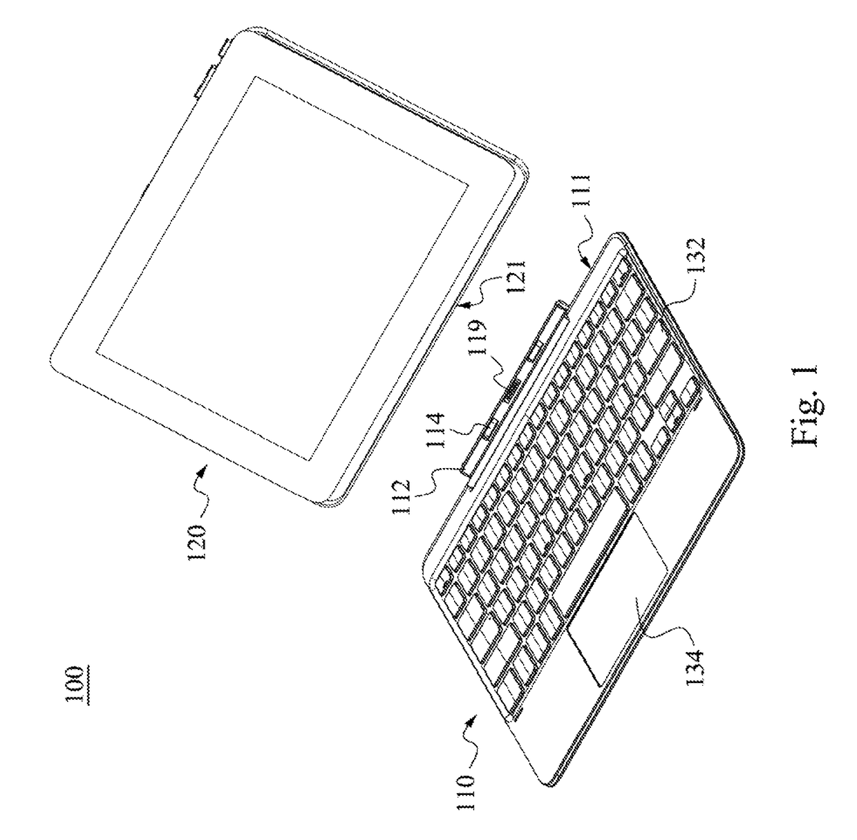
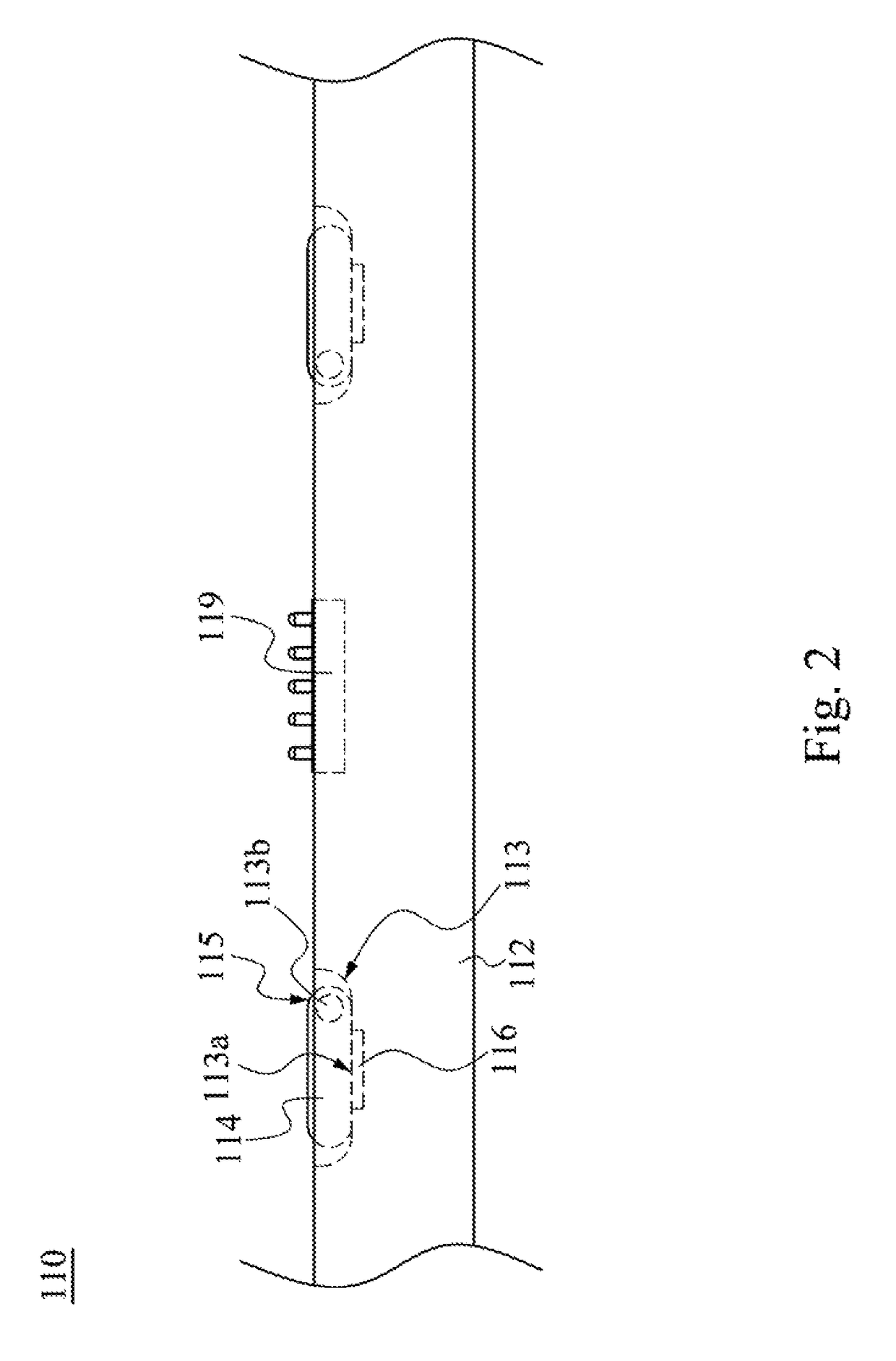
[0029]FIG. 1 is an exploded view of a portable electronic device 100 according to one embodiment of the present invention. FIG. 2 is a partially enlarged view of an expansion assembly 110 shown in FIG. 1. As shown in FIG. 1 and FIG. 2, the portable electronic device 100 includes the expansion assembly 110 and a tablet computer 120. The expansion assembly 110 includes a hinge base 112, a rotating element 114, and a first magnet 116. The hinge base 112 is located on a side 112 of the expansion assembly 110 and has a first concave portion 113. An end 115 of the rotating element 114 is pivoted to the first concave portion 113. The first magnet 116 is located on the hinge base 112, and the position of the first mag...


PUM


Abstract

A portable electronic device includes an expansion assembly and a tablet computer. The expansion assembly includes a hinge base, a rotating element, and a first magnet. The hinge base is located on the expansion assembly and has a first concave portion. The rotating element is pivoted to the first concave portion. The first magnet is located on the hinge base. The position of the first magnet corresponds to the position of the rotating element. The tablet computer includes a housing and a second magnet. The housing has a second concave portion. The position of the second concave portion corresponds to the position of the first concave portion and the second concave portion has an oblique wall. The second magnet is located on the oblique wall and the magnetic force of the second magnet is greater than the magnetic force of the first magnet.

Description

RELATED APPLICATIONS[0001]This application claims priority to Chinese Application Serial Number 201510849664.X, filed Nov. 27, 2015, which is herein incorporated by reference.BACKGROUND[0002]Field of Invention[0003]The present invention relates to a portable electronic device.[0004]Description of Related Art[0005]Generally, a two-in-one detachable laptop computer (i.e., a detachable NB) is composed of a tablet computer and a keyboard device. In order to let users can adjust the inclination of the screen of the tablet computer on the keyboard device after the tablet computer is connected to the keyboard device, a recess is usually designed in a side of the tablet computer and a protruding pillar is usually designed on a side of the keyboard device having a hinge base by manufacturer. When the recess of the tablet computer is coupled to the protruding pillar of the hinge base, the tablet computer may receive a force to rotate the hinge base through the protruding pillar.[0006]However,...

Claims


Application Information

Patent Timeline
Patent Type & Authority Patents(United States)
IPC IPC(8): G06F1/16G06F3/02H04M1/02
CPCG06F1/1616G06F3/0202G06F1/169G06F1/1681G06F1/1669G06F1/1654H04M1/0254G06F1/1632G06F1/1679G06F1/1667G06F1/1626G06F3/03547H04M1/0216
Inventor TSAI, YI-LINGCHENG, KUO-YANG
Owner INVENTEC PUDONG TECH CORPOARTION
Why Eureka
Try Eureka