projector

a projector and projector body technology, applied in the field of projectors, can solve the problems of bending stress, excessive load on the angle adjustment plate, and the inability to apply the technology to the structure in which the leaf spring is not used,

Active Publication Date: 2014-04-03
SEIKO EPSON CORP
View PDF7 Cites 12 Cited by
  • Summary
  • Abstract
  • Description
  • Claims
  • Application Information

AI Technical Summary

Benefits of technology

[0015]In addition, since adjustment is achieved without applying an excessive load on members such as the supporting portion, the base portion, and the clamping portion when adjusting the inclination, the projector which is provided with the adjusting mechanism by suppressing increase in size and weight of the adjusting mechanism and hence the projector without the necessity of excessively reinforcing the respective members may be provided.
[0022]In this configuration, since the exterior housing is provide with the above-described first housing and the second housing, the second housing can be removed easily from the first housing when adjusting the inclination of the projection lens, and the second housing can be mounted on the first housing easily when the adjustment is terminated. Accordingly, members other than the second housing from among the members which constitute the projector need not to be disassembled, so that the adjustment of the inclination of the projection lens can easily achieved and, simultaneously, improvement in appearance of the projector when the second housing is mounted is achieved.
[0025]In this configuration, the second housing, including the above-described cover body and the auxiliary member, is mounted on the first housing by engaging the auxiliary member with the cover body and the first housing. Accordingly, the second housing can be mounted on the first housing easily without providing members such as screws for mounting the second housing or without using a tool or the like.

Problems solved by technology

However, the technology described in JP-A-2010-276895 does not disclose whether the apparatus includes one each of the angle adjusting screw and the angle adjusting plate fixing screw, if there are pluralities of the angle adjusting screws and the angle adjusting plate fixing screws are included, how these screws are arranged two-dimensionally, and hence has a risk of giving an excessive load (bending stress) to the angle adjusting plate depending on the method of adjustment.
In addition, the technology disclosed in JP-A-2010-276895 is the technology to be applied to the bayonet structure using the leaf spring, and has a problem that this technology cannot be applied to the structure in which the leaf spring is not used.

Method used


Image

  • projector
  • projector
  • projector

Examples


Embodiment Construction

[0039]Referring now to the drawings, a projector according to an embodiment will be described. The projector of the embodiment is configured to modulate an optical flux emitted from a light source according to image information and project an image on a projected surface such as a screen. The projector of the embodiment is configured to be capable of stationary installation in which the projector is installed on a desk or the like, hanging installation in which the projector is installed in a state of being inverted upside down in contrast to the stationary installation, and installation in postures different from the stationary installation and the hanging installation.

Principal Configuration of Projector

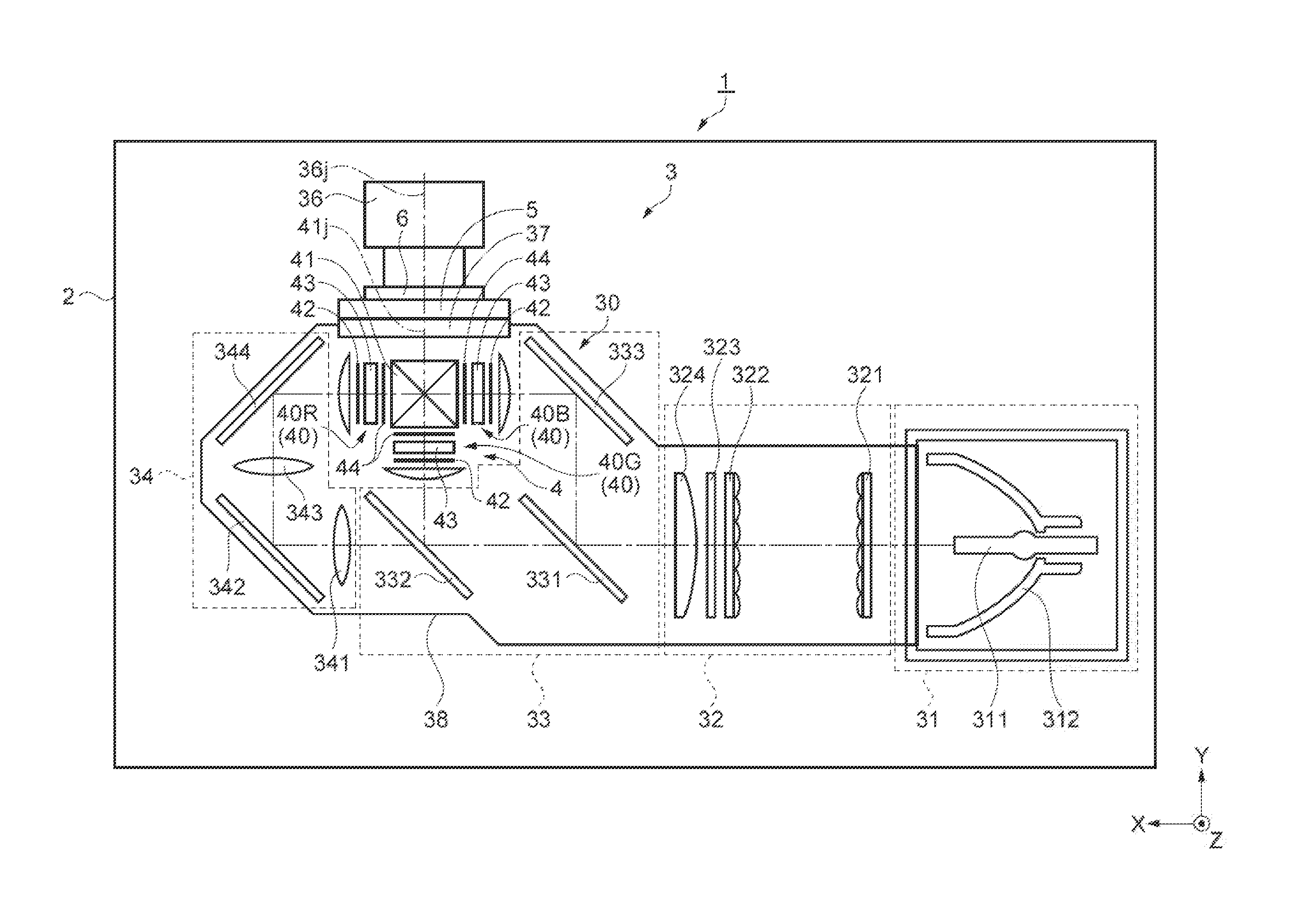
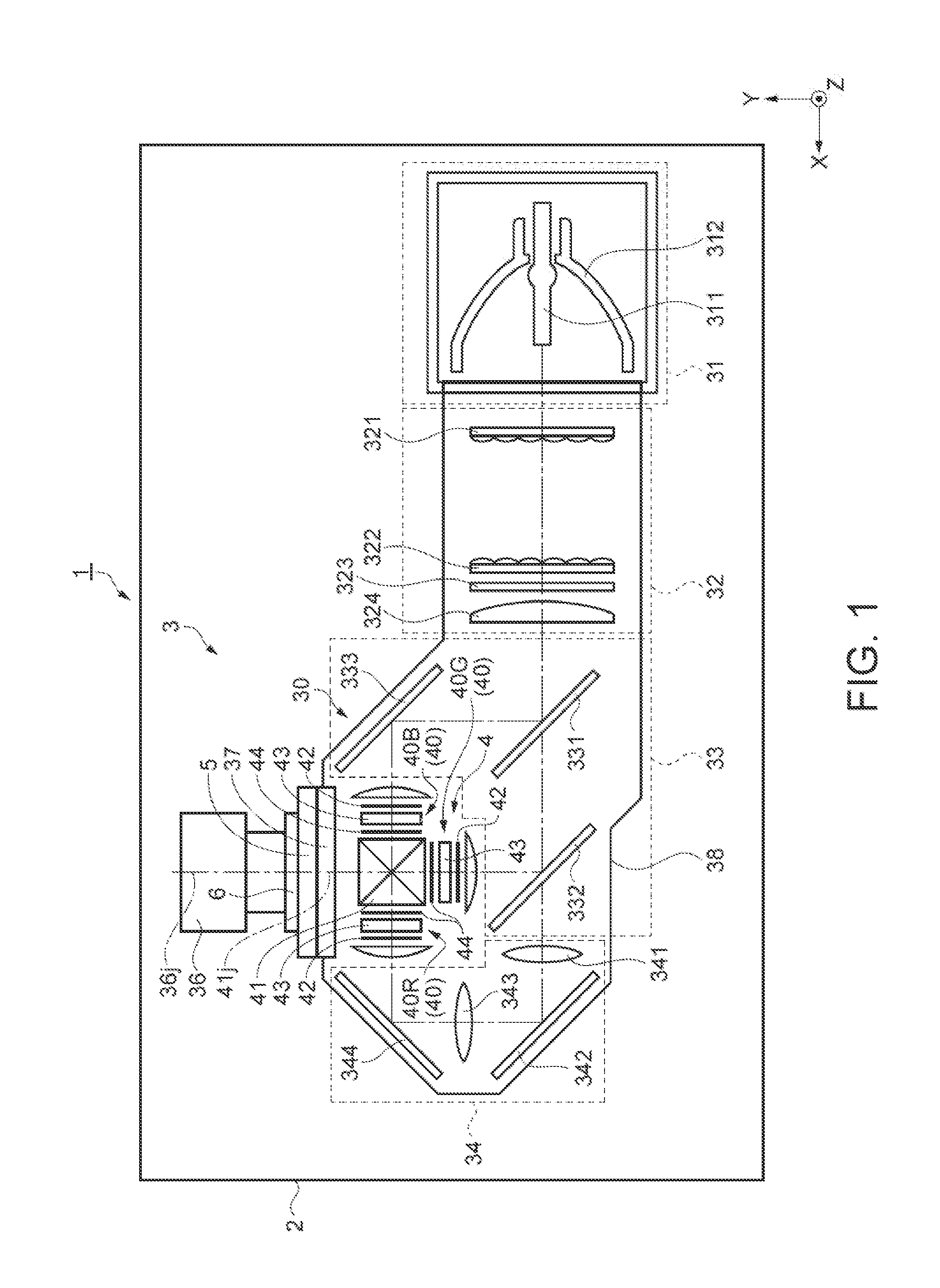
[0040]FIG. 1 is a diagrammatic drawing illustrating a schematic configuration of a projector 1 of the embodiment.

[0041]The projector 1 includes an exterior housing 2 constituting an exterior, a control unit (not illustrated), and an optical unit 3 having a light source apparatus 31...


PUM


Abstract

A projector includes: an optical unit body having a light modulating apparatus configured to modulate an optical flux emitted from a light source according to image information; a projection lens configured to project the optical flux modulated by the light modulating apparatus; and an adjusting mechanism configured to adjust an inclination of the projection lens with respect to the optical unit body. The adjusting mechanism includes; a supporting portion configured to support the projection lens; a base portion configured to constitute part of the optical unit body; a clamping portion configured to clamp the base portion in cooperation with the supporting portion; a fixing member configured to fix the supporting portion to the clamping portion; and adjusting members configured to be capable of adjusting a distance between the base portion and the supporting portion.

Description

CROSS REFERENCE TO RELATED APPLICATIONS[0001]This application claims priority to Japanese Patent Application No. 2012-215818 filed on Sep. 28, 2012, the entire contents of which are incorporated by reference herein.BACKGROUND[0002]1. Technical Field[0003]The present invention relates to a projector.[0004]2. Related Art[0005]In the related art, a projector including a light modulating apparatus configured to modulate an optical flux emitted from a light source and a projection lens configured to project the modulated optical flux is known. In recent years, a projector capable of a large-screen projection and projecting on a projecting surface arranged in the proximity of the projector (proximity projection) is required. In order to achieve the large-screen or the proximity projection, the projection lens is increased in size and weight, and hence a phenomenon in which the projection lens falls (inclines) forward under its own weight with respect to a member to which the projection le...

Claims


Application Information

Patent Timeline
Patent Type & Authority Applications(United States)
IPC IPC(8): G03B21/14
CPCG03B21/142G02B7/022G02B7/023
Inventor NEMURA, AKIRAOKOSHI, MASAYUKI
Owner SEIKO EPSON CORP
Why Eureka
Try Eureka