Driving force distribution apparatus

a technology of driving force and distribution apparatus, which is applied in mechanical equipment, transportation and packaging, and gearing, etc., can solve the problems of increasing and the rigidity of the ring gear is difficult to secure sufficiently, so as to increase the size and weight of the apparatus

Active Publication Date: 2021-07-13
JTEKT CORP
View PDF6 Cites 0 Cited by
  • Summary
  • Abstract
  • Description
  • Claims
  • Application Information

AI Technical Summary

Benefits of technology

[0006]It is one object of the present invention to provide a driving force distribution apparatus in which the support rigidity of an orthogonal gear pair can be secured while suppressing an increase in the size and weight of the apparatus.
[0017]According to the driving force distribution apparatus of the aspect described above, the support rigidity of the orthogonal gear pair can be secured while suppressing the increase in the size and weight of the apparatus.

Problems solved by technology

In this structure, the ring gear is cantilevered, and therefore the support rigidity of the ring gear is difficult to secure sufficiently.
When the size of the bearing is increased to secure the support rigidity of the ring gear, the size and weight of the apparatus may increase.

Method used


Image

  • Driving force distribution apparatus
  • Driving force distribution apparatus
  • Driving force distribution apparatus

Examples


first embodiment

[0030]the present invention is described with reference to FIG. 1 to FIG. 4.

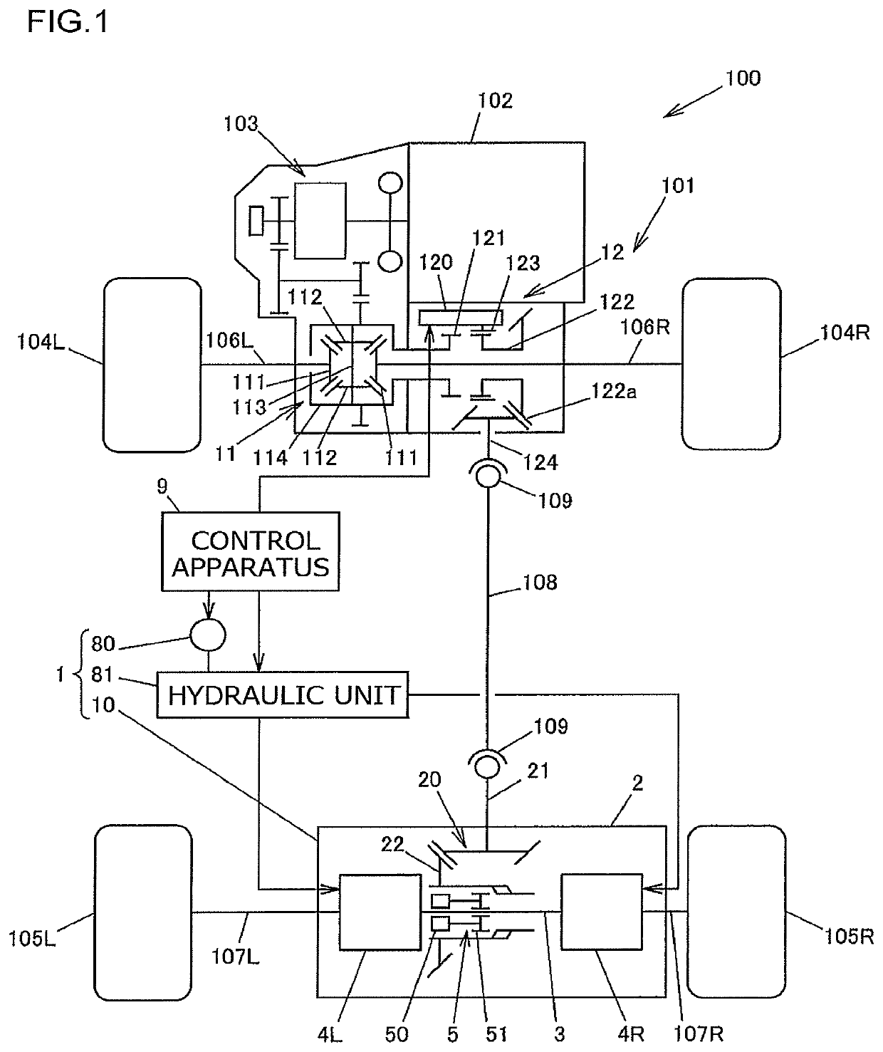
[0031]FIG. 1 is a structural diagram schematically illustrating an example of the structure of a four-wheel drive vehicle on which a driving force distribution apparatus according to the first embodiment of the present invention is mounted.

[0032]A four-wheel drive vehicle 100 includes an engine 102, a transmission 103, front wheels 104R and 104L, rear wheels 105R and 105L, a driving force transmission system 101, and a control apparatus 9. The engine 102 serves as a drive source configured to generate a driving force for traveling. The front wheels 104R and 104L serve as a pair of right and left main driving wheels. The rear wheels 105R and 105L serve as a pair of right and left auxiliary driving wheels. The driving force transmission system 101 is configured to transmit the driving force of the engine 102 to the front wheels 104R and 104L and the rear wheels 105R and 105L.

[0033]The four-wheel drive vehicle ...


PUM


Abstract

A driving force distribution apparatus includes an orthogonal gear pair constituted by a pinion gear shaft and a ring gear member, a casing that houses the orthogonal gear pair, an intermediate rotational member coaxially rotatable relative to the ring gear member, a clutch member configured to couple the ring gear member and the intermediate rotational member to each other, and first and second driving force adjustment mechanisms configured to adjust a driving force to be transmitted from the intermediate rotational member to first and second output rotational members. The ring gear member has a ring gear portion and a tubular portion. At two positions between which the ring gear portion is interposed in an axial direction, the tubular portion) is rotatably supported by a pair of bearings.

Description

INCORPORATION BY REFERENCE[0001]The disclosure of Japanese Patent Application No. 2017-020248 filed on Feb. 7, 2017 including the specification, drawings and abstract, is incorporated herein by reference in its entirety.BACKGROUND OF THE INVENTION1. Field of the Invention[0002]The present invention relates to a vehicle driving force distribution apparatus configured to output an input driving force from first and second output rotational members.2. Description of the Related Art[0003]Hitherto, a driving force distribution apparatus configured to output an input driving force from first and second output rotational members is mounted on, for example, a four-wheel drive vehicle. This type of driving force distribution apparatus includes a driving force distribution apparatus configured such that the distribution ratio between the driving force to be output from the first output rotational member and the driving force to be output from the second output rotational member can be adjuste...

Claims


Application Information

Patent Timeline
Patent Type & Authority Patents(United States)
IPC IPC(8): F16H48/19F16H1/14F16D25/10B60K17/02F16D25/0638
CPCF16H48/19B60K17/02F16D25/0638F16D25/10F16H1/14B60K17/08B60K17/34B60K2023/0841B60K17/344B60K23/0808B60K2023/085F16D25/082
Inventor FUJII, NORIYUKI
Owner JTEKT CORP
Why Eureka
Try Eureka