Rolling bearing

Inactive Publication Date: 2014-03-20
JTEKT CORP
View PDF0 Cites 0 Cited by
  • Summary
  • Abstract
  • Description
  • Claims
  • Application Information

AI Technical Summary

Benefits of technology

The invention aims to create a rolling bearing that can use both solid and liquid lubricants without causing larger and heavier bearings. The design suppresses the negative effects of using solid lubricants and reduces the resistance of using liquids.

Problems solved by technology

If an amount of a liquid lubricant (mainly, lubricating oil) supplied to a rolling bearing becomes excessively large, stirring resistance of the lubricant during the rotation of the bearing increases, and thus it becomes difficult to achieve lower torque.
On the other hand, in the case where the solid lubricant is used instead of the liquid lubricant, there are problems that, for example, the solid lubricant is inferior in heat dissipation characteristics to the liquid lubricant and abrasion powder may adversely affect lubrication.

Method used


Image

  • Rolling bearing
  • Rolling bearing
  • Rolling bearing

Examples


Embodiment Construction

[0016]Embodiments of the invention will be described below.

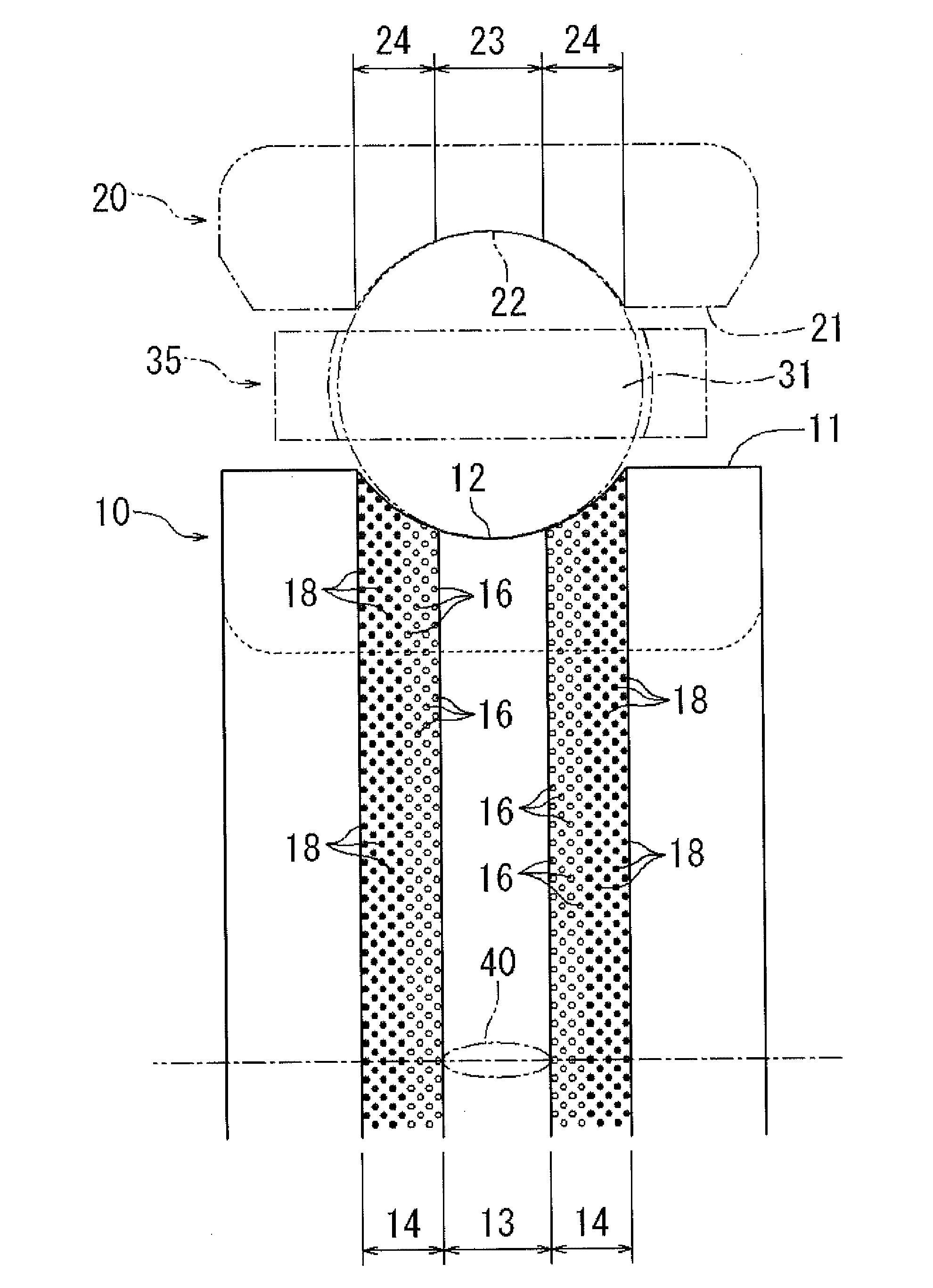
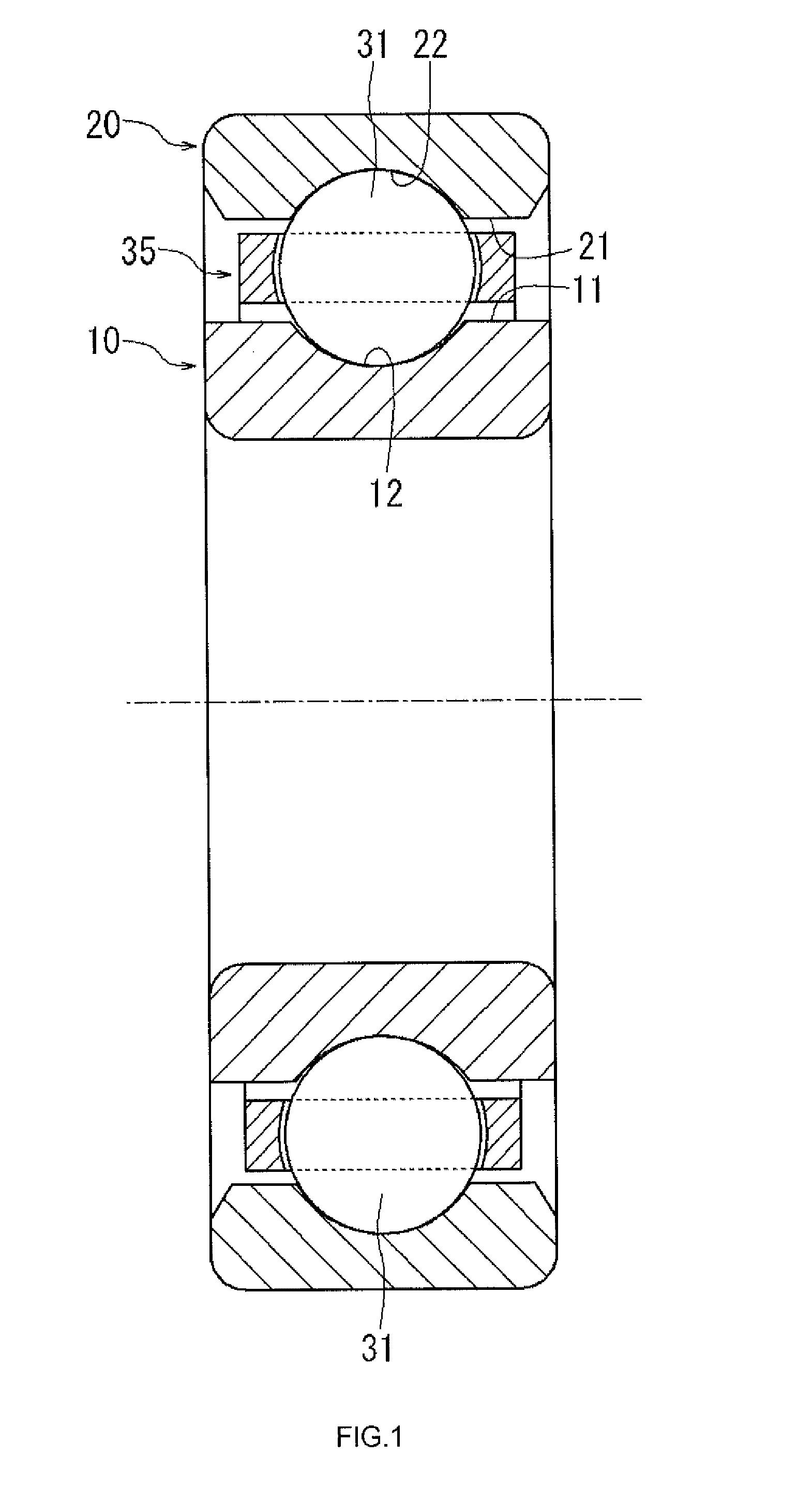
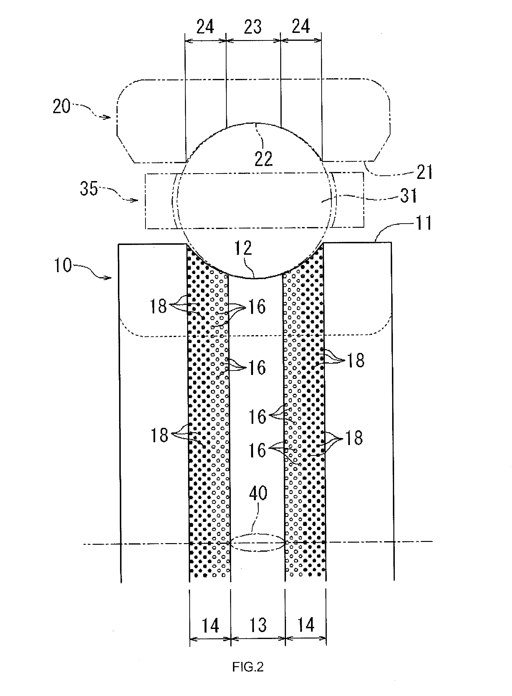
[0017]An embodiment of the invention will be described with reference to the accompanying drawings. In the present embodiment, a case where a deep groove ball bearing is used as a rolling bearing will be described. As illustrated in FIG. I, the deep groove ball bearing used as the rolling bearing includes an inner ring 10, an outer ring 20, a plurality of balls 31 used as rolling elements, and a cage 35. The inner ring 10 is formed in a cylindrical shape, and has an inner ring raceway surface 12 that is formed in an axially center portion of an outer peripheral face 11 and that defines an arc-shaped annular groove.

[0018]The outer ring 20 is formed in a cylindrical shape and has an inner diameter that is larger than an outer diameter of the inner ring 10, and is arranged radially outward of the inner ring 10 via an annular space so as to be concentric with the inner ring 10. The outer ring 20 has an outer ring raceway surface...


PUM


Abstract

A rolling bearing includes an inner ring, an outer ring, and a plurality of rolling elements. A large number of inside dimples in which a liquid lubricant is retained and a large number of outside dimples in which a solid lubricant is retained are formed in at least one of an inner ring raceway surface and an outer ring raceway surface. The inside dimples are formed in a contact region at which the raceway surface contact the rolling elements or in a section of each non-contact region, the section being close to the contact region. The outside dimples are formed outside a portion in which the inside dimples are formed.

Description

INCORPORATION BY REFERENCE[0001]The disclosure of Japanese Patent Application No. 2012-206812 filed on Sep. 20, 2012 including the specification, drawings and abstract, is incorporated herein by reference in its entirety.BACKGROUND OF THE INVENTION[0002]1. Field of the Invention[0003]The invention relates to a rolling bearing.[0004]2. Description of Related Art[0005]If an amount of a liquid lubricant (mainly, lubricating oil) supplied to a rolling bearing becomes excessively large, stirring resistance of the lubricant during the rotation of the bearing increases, and thus it becomes difficult to achieve lower torque. In order to suppress an increase in the stirring resistance of the lubricating oil, for example, a rolling bearing described in Japanese Patent Application Publication No. 2012-87864 (JP 2012-87864 A) has been used. According to JP 2012-87864 A, an inner ring and an outer ring are provided with respective bearing ring extension portions extending in an axial direction, ...

Claims


Application Information

Patent Timeline
IPC IPC(8): F16C33/66
CPCF16C33/6651F16C33/6696F16C19/06F16C33/585F16C33/6648
Inventor SUZUKI, MASAHIROMURATA, JUNJIYAMAKAWA, KAZUYOSHISAITO, TOSHIYUKI
Owner JTEKT CORP
Why Eureka
Try Eureka