Differential adjustment apparatus

a technology of differential adjusters and adjustment apparatuses, which is applied in the direction of mechanical control devices, gearing, instruments, etc., can solve the problems of large and bulky differential adjuster designs in the market, inability to use miniature mechanical devices such as mirror mounts or fiber optic alignment systems, and inability to achieve proper optical adjustment of optical components. , to achieve the effect of reducing the amount of force and increasing the overall size and/or weight of the assembly

Inactive Publication Date: 2005-03-31
THORLABS INC
View PDF8 Cites 7 Cited by
  • Summary
  • Abstract
  • Description
  • Claims
  • Application Information

AI Technical Summary

Benefits of technology

[0011] In accordance with the present invention, a differential adjuster (“adjuster”) is presented that can be miniaturized and incorporated in an assembly with a component holder and / or a component mount such that it does not dramatically increase the overall size and / or weight of the assembly. The small form factor of the differential adjuster is accomplished by utilizing a tool, such as a screwdriver or hex wrench, for example, to activate the differential drive mechanism of the adjuster, thus eliminating the need for at least one large and / or bulky knob. The use of a tool for activating the drive mechanism also decreases the amount of force that is transmitted from the hand of the user to the device due to the fact that the adjuster interface tool is not rigidly attached to the adjuster and / or mount. Adjustments to the component position and orientation can thus be made predictably by adjusting the fine control of the differential adjuster with a tool.
[0013] A differential adjuster according to some other embodiments of the present invention includes an intermediate actuator sleeve including a first threaded surface and a second threaded surface of a different pitch; a main body engaged with the first threaded surface of the intermediate actuator sleeve, the main body including a threaded surface to provide a course adjustment; and a push-rod engaged with the second threaded surface of the intermediate actuator sleeve and coupled to the main body to restrict the relative rotational motion between the push-rod and the main body, wherein the main body includes a coarse tool interface.
[0017] The various embodiments of the invention allow for a miniaturization of differential adjusters while retaining the ability to precisely adjust the adjuster through the use of, for example, a manual or motorized tool and / or knob. This is accomplished, in part, by displacing one or both of the knobs normally found on a typical differential adjuster and replacing the knob or knobs with a tool interface and / or tool connection located near to or inside the main body of the differential adjuster for the fine control, and located on, in, or near the end of the differential adjuster for the coarse adjustment. In addition, the tool interfaces can be made small, which allows for a further miniaturization of the overall differential adjuster. As a consequence, both the overall length and the bulk of the differential adjuster can be reduced, allowing for more precise adjustments of the differential adjuster without the consequent unwanted movement due to the size and / or bulk of typical differential adjusters found in the art. One tool that was identified as providing excellent results in terms of minimizing the transmission of unwanted motion from the user's hand to the device being adjusted was the balldriver style hex Allen wrench sold by Bondhus Corporation.

Problems solved by technology

Considerable effort is often expended in obtaining a proper optical adjustment of the optical components to facilitate the desired optical alignment.
However, typical differential adjuster designs in the market are too large and bulky to be of practical use in miniature mechanical devices such as mirror mounts or fiber optic alignment systems.
The relatively large mass and long lever arm of the typical differential adjuster, when mounted in a relatively small mechanical device such as a mirror mount, introduce significant problems in addition to just the simple problem of occupying too much space.
For example, when a user touches the adjuster, its long length provides a lever arm that introduces a torque that disturbs the mount, which in turn disturbs the alignment of the mirror, causing the reflected light field reflected off the mirror to move erratically.
This erratic motion inhibits the ability of the user to take full advantage of the high sensitivity of the adjuster / mount combination.
In some cases, such erratic movement of the beam may result in a hazardous environment, potentially causing damage to equipment and injury to personnel.
Typically a 1″ mirror would not be used when building a miniaturized optical system, however, because differential adjusters have in the past been so large as to make it impractical to use them on mirror mounts that are designed for smaller optics, suppliers for smaller mirror mounts that are offered with differential adjusters have not been located.
Incorporating multiple knobs into the differential adjuster increases the bulk and size of the overall adjuster, and further exacerbates the problems discussed above.
In some systems, mounts utilizing adjusters have been bulky and heavy in order to offset the deficiencies in the adjuster.
This solution results in bulky and heavy mounts that are difficult to arrange in high density optical systems.
The use of a tool for activating the drive mechanism also decreases the amount of force that is transmitted from the hand of the user to the device due to the fact that the adjuster interface tool is not rigidly attached to the adjuster and / or mount.

Method used


Image

  • Differential adjustment apparatus
  • Differential adjustment apparatus
  • Differential adjustment apparatus

Examples


Embodiment Construction

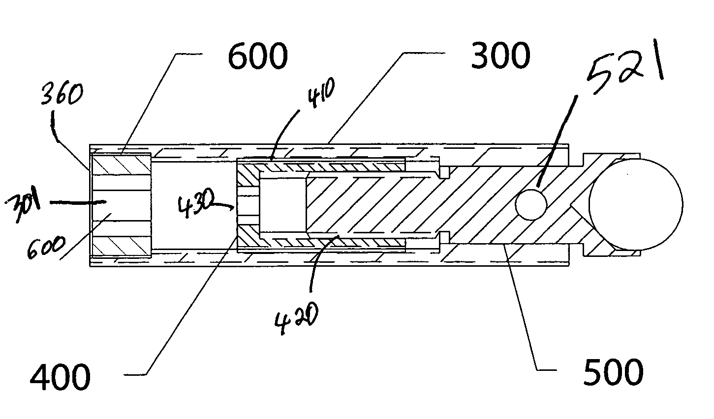
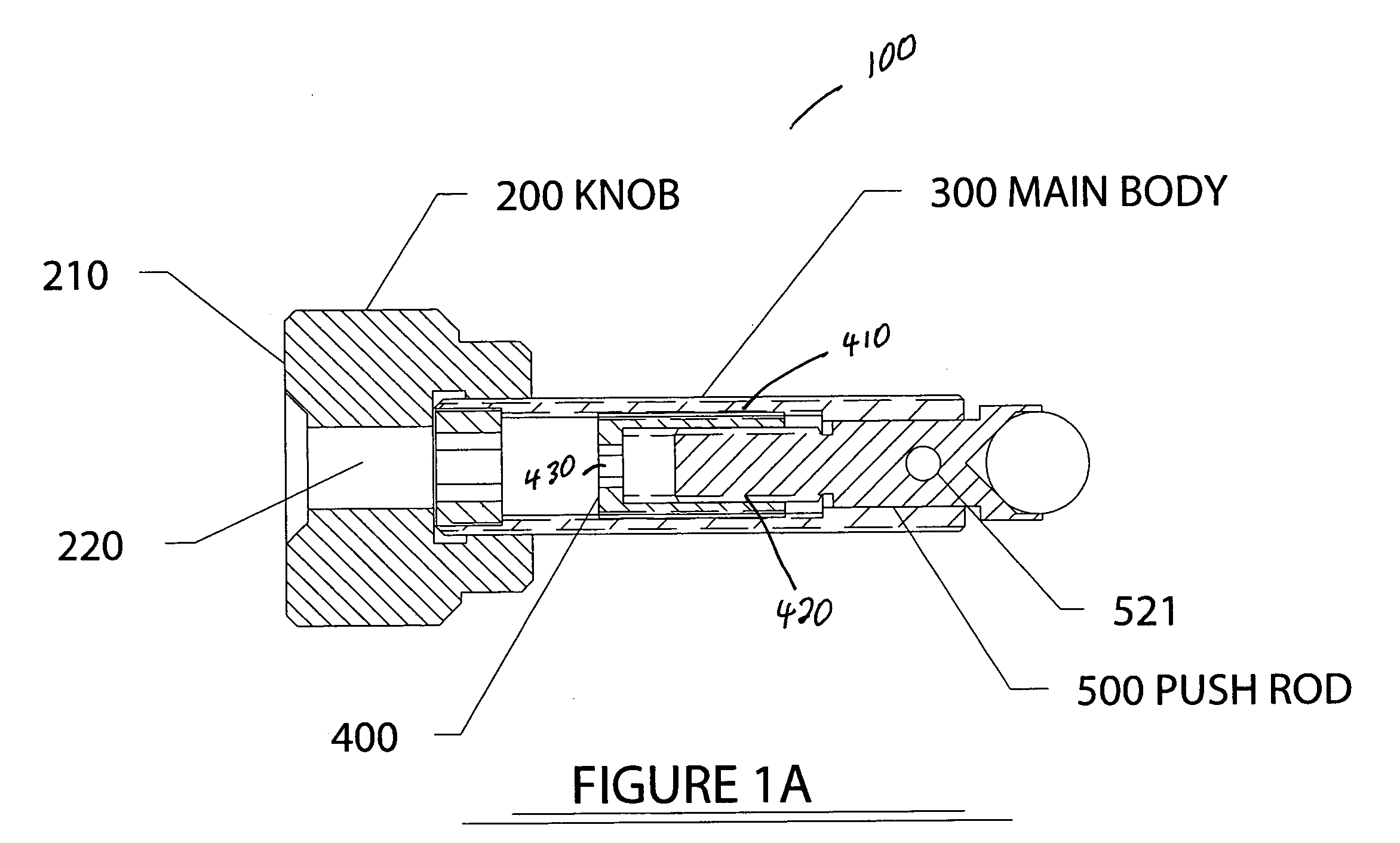
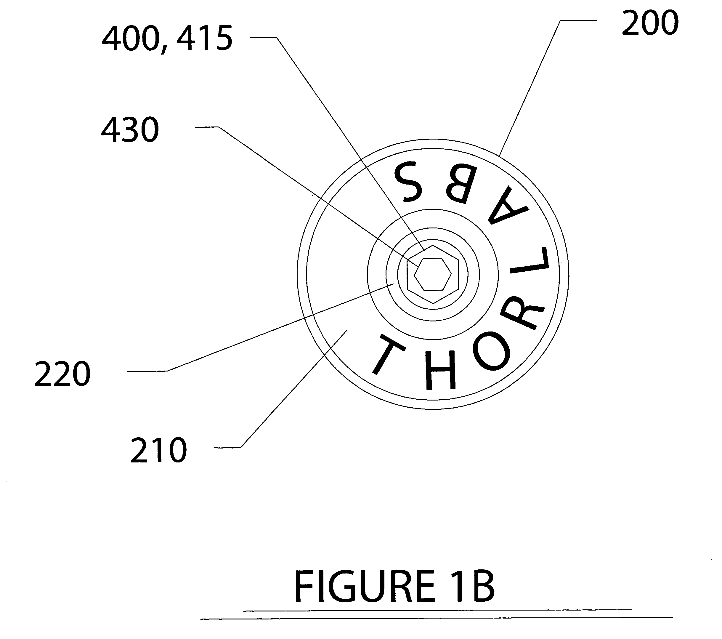
[0033]FIG. 1A shows a side cross-sectional view of a differential adjuster 100 (“adjuster 100”) according to some embodiments of the present invention. Adjuster 100 includes an intermediate actuator sleeve 400 with a first threaded surface 410 and a second threaded surface 420. A push rod 500 is coupled to second threaded surface 420 of intermediate actuator sleeve 400 and is in communication with threads on second threaded surface 420. Intermediate actuator sleeve 400 is coupled to a housing 300, which in FIG. 1A is shown as main body 300. In some embodiments, housing 300 can be any housing, including a component mount or other device.

[0034] Push rod 500 is coupled to main body 300 in order to be rotationally constrained with respect to main body 300. In the embodiment shown in FIG. 1A, push rod 500 includes a dowel pin 521 that serves to restrict its rotation with respect to main body 300. In general, any coupling between push rod 500 and main body 300 (or a housing) that constra...


PUM


Abstract

A differential adjuster that utilizes a tool interface for affecting either a coarse adjustment or a fine adjustment is presented. In accordance with some embodiments of the present invention, a differential adjuster includes an intermediate actuator sleeve with a tool interface to accommodate a tool for performing fine adjustments. In some embodiments, a differential adjuster includes a main body with a tool interface to accept a tool for performing coarse adjustments. By utilizing a tool interface, rather than a knob, embodiments of the differential adjuster according to the present invention can be formed with small form factors.

Description

BACKGROUND [0001] 1. Technical Field [0002] The present invention relates to differential adjusters, and, in particular, to a miniaturized differential adjustment apparatus that allows for minute, precise adjustments, for example, of optical components mounted in an adjustable mechanical mount used for precision alignment. [0003] 2. Discussion of Related Art [0004] Investigations of optical phenomena and testing of optical systems often require increasingly precise orientations of optical elements such as mirrors, lenses, filters, optical fibers, and other optical elements. Research into optical transmission of data, for example, requires precisely oriented components to manipulate light of various wavelengths into and out of optical wave-guides, which may have core sizes of less than about 0.010 mm. In research environments, various components, for example mirrors, filters and / or lenses, can be mounted on an optical mount for use on an optics table. Considerable effort is often exp...

Claims


Application Information

Patent Timeline
IPC IPC(8): G05G1/08G05G1/54G05G1/56
CPCG05G1/54G05G1/56Y10T74/20474Y10T74/18992G05G23/00
Inventor CABLE, ALEX EZRAMILLS, JASON MATHEW
Owner THORLABS INC
Why Eureka
Try Eureka