
Shipbuilding steel plate cutting device

A technology for cutting devices and steel plates, applied in positioning devices, driving devices, clamping, etc.

Active Publication Date: 2016-08-17
YANGFAN GROUP
View PDF5 Cites 12 Cited by
  • Summary
  • Abstract
  • Description
  • Claims
  • Application Information

AI Technical Summary

Problems solved by technology

[0004] The problem to be solved by the present invention is that the equipment in the prior art is the problem that the workpiece is rotated for cutting

Method used


Image

  • Shipbuilding steel plate cutting device

Examples


Embodiment Construction

[0016] The present invention will be further described below in conjunction with the accompanying drawings and embodiments.

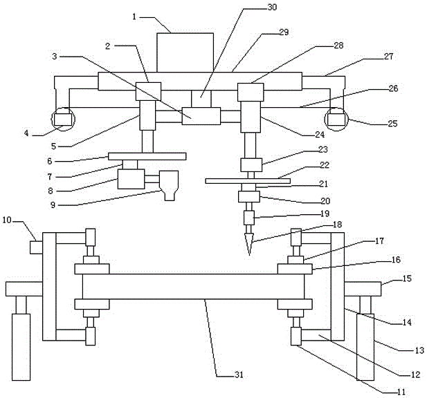
[0017] The present invention is a steel plate cutting device for ships, comprising a frame 1, a first slider 2, a double-head cylinder 3, a first motor 4, a first cylinder 5, a first linear motor 6, a first moving block 7, and a second motor 8. Hair dryer 9, controller 10, fourth cylinder 11, support block 12, fifth cylinder 13, pillar 14, support plate 15, splint 16, fisheye bearing 17, cutter 18, third cylinder 19, fourth motor 20, the second moving block 21, the second linear motor 22, the third motor 23, the second cylinder 24, the roller 25, the rope 26, the wheel frame 27, the second slider 28, the first slide rail 29 and the bearing 30, The first slide rail 29 is installed under the shelf 1, the first slide block 2 and the second slide block 28 are installed on the first slide rail 29, the first cylinder 5 is installed under the first slide block...


PUM


Abstract

The invention relates to a shipbuilding steel plate cutting device. The shipbuilding steel plate cutting device comprises a rack, a first sliding block, a double-end cylinder, first motors, a first cylinder, a first linear motor, a first moving block, a second motor, a blower, a control, fourth cylinders, supporting blocks, fifth cylinders, supporting columns, supporting plates, clamping plates, knuckle bearings, a cutting knife, a third cylinder, a fourth motor, a second moving block, a second linear motor, a third motor, a second cylinder, ropes, roller carriers, a first sliding rail and a supporting base, wherein the first sliding rail is arranged below the rack; the first sliding block and the second sliding block are arranged on the first sliding rail; the first cylinder is arranged below the first sliding block; the first linear motor is arranged below the first cylinder; the first moving block is arranged on the first linear motor; the second motor is arranged below the first moving block; the output shaft of the second motor is provided with the blower; and the second cylinder is arranged below the second sliding block. The shipbuilding steel plate cutting device has the advantages that a cutter can rotate and move to cut a shipbuilding steel plate.

Description

technical field [0001] The invention relates to a ship plate cutting device, which belongs to the technical field of mechanical equipment. Background technique [0002] The development process of modern shipbuilding technology is a process from manual operation to mechanization and automation, which improves the hull construction from the sporadic and bulk method used in the past to the segmented assembly method, which greatly improves the shipbuilding efficiency. Due to the complex structure and shape of the hull, Due to the large size and weight of some steel plates, it is difficult to move the steel plate workpiece. Most of the equipment is cut by rotating the workpiece, so the required rotational torque is large, the power consumption is large, and the work efficiency is low. In order to solve the above difficulties, it is necessary to develop a cutting device in which the cutter rotates and moves to cut the steel plate of the ship. Contents of the invention [0003] ...

Claims


Application Information

Patent Timeline
IPC IPC(8): B23B39/00B23B47/00B23B47/26B23Q3/08B23Q5/10B23Q11/00
CPCB23B39/00B23B47/00B23B47/26B23Q3/08B23Q5/10B23Q11/005
Inventor 刘在良夏小浩赖祥华叶步永
Owner YANGFAN GROUP
Learn More