Complex-structural well formation flow and internal flow coupled flow experiment system

A technology of complex structure and experimental system, applied in wellbore/well components, construction, measurement, etc., can solve problems such as lack of formation simulation system and inability to simulate the coupling of formation flow and wellbore flow of oil, gas and water seepage

Inactive Publication Date: 2014-01-15
SOUTHWEST PETROLEUM UNIV
View PDF6 Cites 12 Cited by
  • Summary
  • Abstract
  • Description
  • Claims
  • Application Information

AI Technical Summary

Problems solved by technology

[0007] None of the existing experimental devices has a formation simulation system, which cannot simulate the seepage of oil, gas and water in the formation and the coupling of formation flow and wellbore flow

Method used


Image

  • Complex-structural well formation flow and internal flow coupled flow experiment system
  • Complex-structural well formation flow and internal flow coupled flow experiment system
  • Complex-structural well formation flow and internal flow coupled flow experiment system

Examples


Embodiment 1

[0061] Embodiment 1 (natural energy extraction of oil-gas-water three-phase closed oil and gas reservoir):

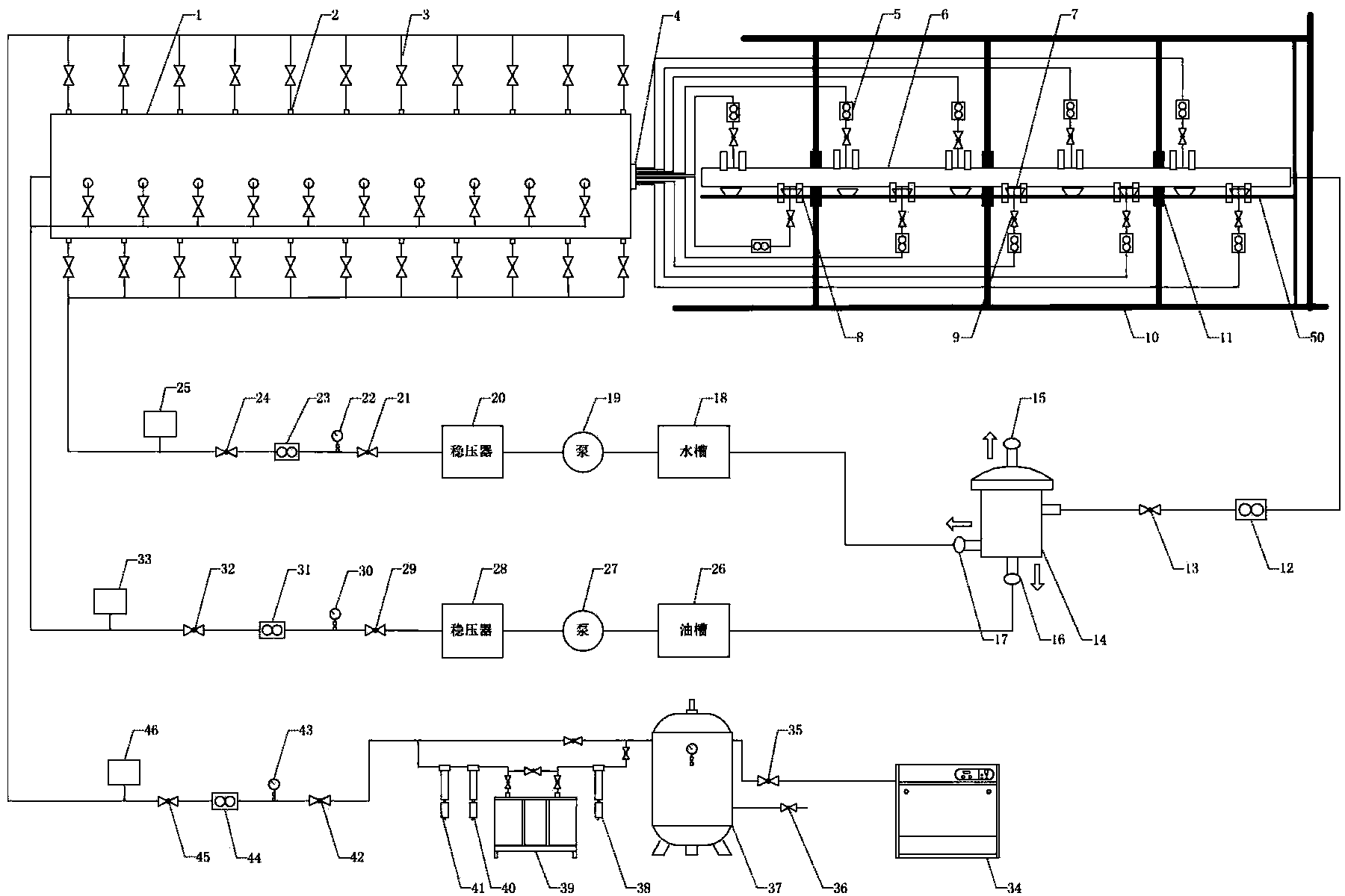
[0062] Before the experiment starts, set the initial state of the reservoir, close the throttle valve 9 on the outflow pipeline of seepage tank 1, open the first control valve 21 and the second control valve 24, inject water into the seepage tank 1, and close the first control valve after reaching a predetermined value. Control valve 21 and second control valve 24; open first control valve 29 and second control valve 32, inject oil into seepage tank 1, close first control valve 29 and second control valve 32 after reaching a predetermined value; open first The control valve 42 and the second control valve 45 inject gas into the seepage tank 1, and close the first control valve 42 and the second control valve 45 after reaching a predetermined value; start the experiment after the initial state of the seepage tank 1 is set, and open the seepage tank to flow out The thrott...

Embodiment 2

[0063] Example 2 (oil-water two-phase large-scale edge-bottom water displacement reservoir natural energy recovery):

[0064] Before the experiment starts, set the initial state of the reservoir, close the throttle valve 9 on the outflow pipeline of seepage tank 1, open the first control valve 21 and the second control valve 24, inject water into the seepage tank, and close the first control valve after reaching the predetermined value. valve 21 and the second control valve 24; open the first control valve 29 and the second control valve 32, inject the oil into the seepage tank, and close the first control valve 29 and the second control valve 32 after reaching a predetermined value; the initial state of the seepage tank is set Start the experiment after being set, open the throttle valve 9 on the seepage tank outflow pipeline, the fluid in the seepage tank flows into the horizontal simulated wellbore 48, then flows into the equivalent horizontal well simulated wellbore 6 throu...


PUM


Abstract

The invention discloses a complex-structural well formation flow and internal flow coupled flow experiment system. The complex-structural well formation flow and internal flow coupled flow experiment system comprises a seepage tank, a horizontal well simulated wellbore installed in the seepage tank and provided with a first jet hole, an equivalent horizontal well simulated wellbore provided with a second jet hole correspondingly communicated with the first jet hole, a water-phase feeding system, an oil-phase feeding system, a gas-phase feeding system and a three-phase flowmeter, wherein a throttling valve is arranged on a pipe communicated with the first jet hole and the second jet hole, the equivalent horizontal well simulated wellbore is provided with a pressure transmitter, a sliding rod is installed on a support, and a particle imaging test system is installed on the sliding rod. The water-phase feeding system, the oil-phase feeding system and the gas-phase feeding system are communicated with the seepage tank. Two of outlets of the three-phase flowmeter are respectively communicated with the water-phase feeding system and the oil-phase feeding system, the other outlet of the three-phase flowmeter is communicated with the equivalent horizontal well simulated wellbore, and the three-phase flowmeter is further provided with the gas-phase outlet end. A formation system and the horizontal well simulated wellbore which are simulated by the system conform to the actual situation, and the complex-structural well formation flow and internal flow coupled flow experiment system has representativeness so that a performed experiment has good guiding significance on actual production.

Description

technical field [0001] The invention relates to a three-dimensional flow physical model of a well with a complex structure, and more specifically relates to a coupling flow experiment system for formation flow and flow in a pipe of a well with a complex structure. Background technique [0002] With the development of drilling technology, the application of complex structure wells is becoming more and more extensive, which plays an important role in improving the productivity of oil and gas wells and tapping the remaining oil potential. However, its flow law and its influence on digital modeling, well testing and reservoirs are still unclear, and the current research mainly focuses on theoretical derivation and simulation of regular well flow field by using the principle of hydropower similarity; for complex structure wells and formation coupling Flow is primarily studied by simplifying the well structure. [0003] Due to the limitations of electrical simulation, it cannot r...

Claims


Application Information

Patent Timeline
Patent Type & Authority Applications(China)
IPC IPC(8): E21B49/00E21B47/11E21B47/00E21B47/06
Inventor 吴锋胡晓华李溢龙李晓平鲁新便曹丽娜姚卓成刘启国
Owner SOUTHWEST PETROLEUM UNIV
Why Eureka
Try Eureka