Brush holder apparatus and system

a brush holder and apparatus technology, applied in the direction of current collectors, dynamo-electric components, dynamo-electric machines, etc., can solve the problems of carbon brushes, wear due to friction, need periodic replacement, and heavy and unwieldy conventional brush holders,

Active Publication Date: 2017-05-09
GENERAL ELECTRIC CO
View PDF35 Cites 5 Cited by
  • Summary
  • Abstract
  • Description
  • Claims
  • Application Information

AI Technical Summary

Benefits of technology

[0049]One advantage provided by the present invention, is that the RFID tag 1000 can be added to an existing brush holder, so that the brush itself does not have to be modified. As the brush is a “consumable item”, this provides an economic advantage to the user, because they can purchase, use and replace standard brushes for low cost. The apparatus and system herein described also avoids the use of extra wires attached to the brush holder or brush itself. The “extra wires” approach has potential for additional shorting paths and excessively noisy signals from the adjacent energized components. It also interferes with visual inspection and the brush changing operation. The present invention also provides the advantage of eliminating sensors physically attached or embedded within the brush. This reduces cost and eliminates the possibility that the brush will be adversely affected when sliding along the brush holder, as any attachment onto the brush presents the possibility for the brush to get stuck in the brush holder. If a brush gets stuck and stops sliding down the brush holder, a gap will form between the brush and collector, and this could lead to undesired arcing and eventual machine failures. It can also be fully operational when the rest of the dynamoelectric machine is not in operation.

Problems solved by technology

As the brushes are stationary with respect to the rotating elements, the brushes, which are made of carbon, wear due to friction and need periodic replacement.
Conventional brush holders can be heavy and unwieldy, making brush replacement both difficult and dangerous.

Method used


Image

  • Brush holder apparatus and system
  • Brush holder apparatus and system
  • Brush holder apparatus and system

Examples


Embodiment Construction

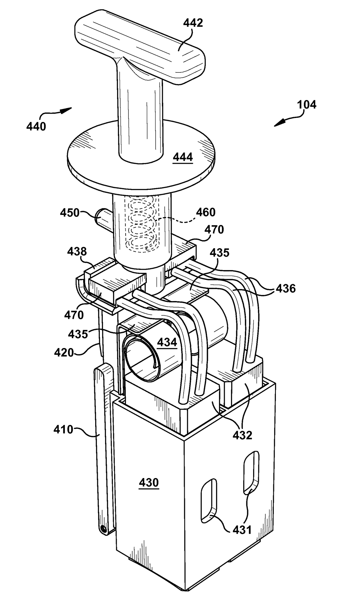
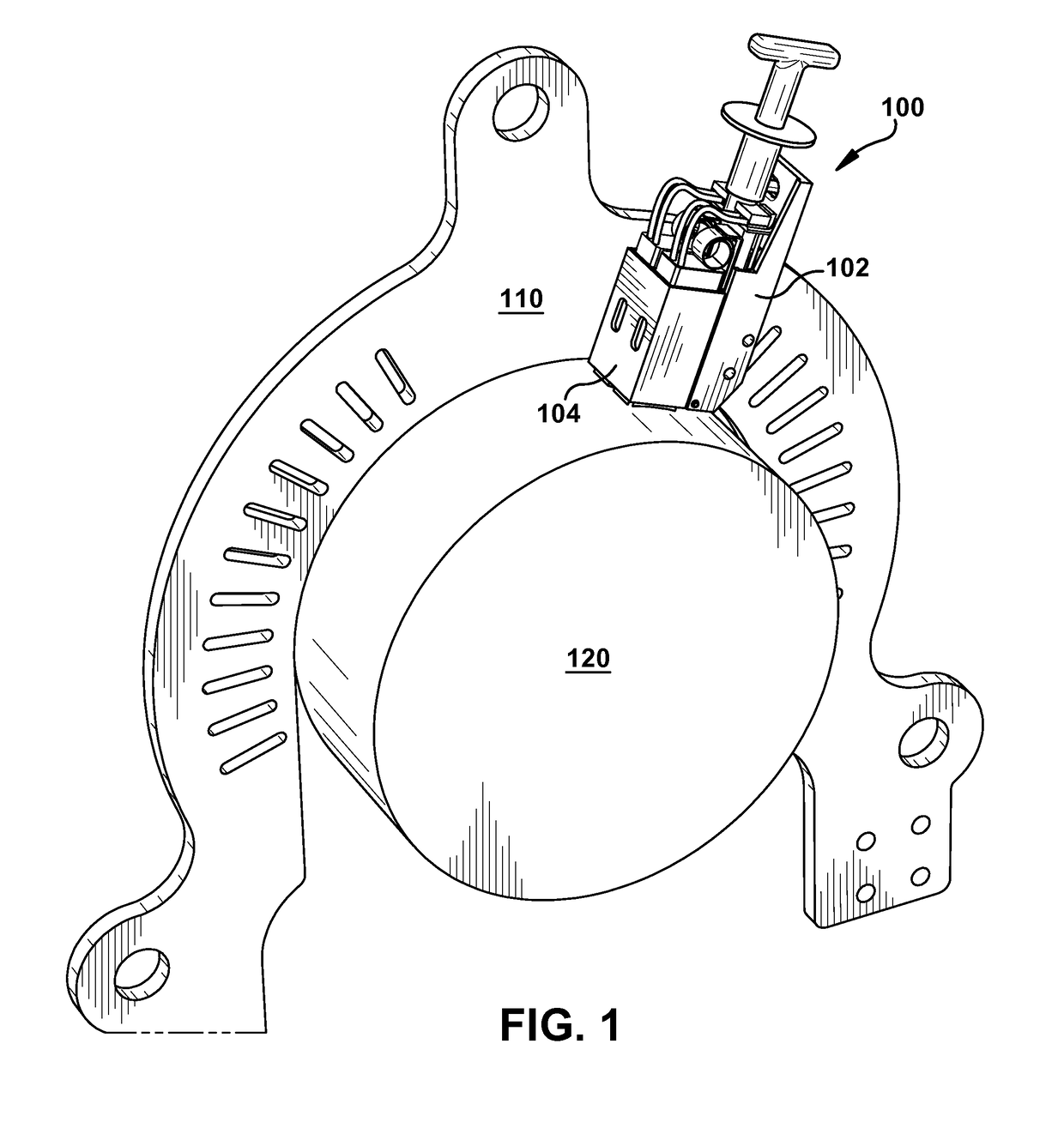
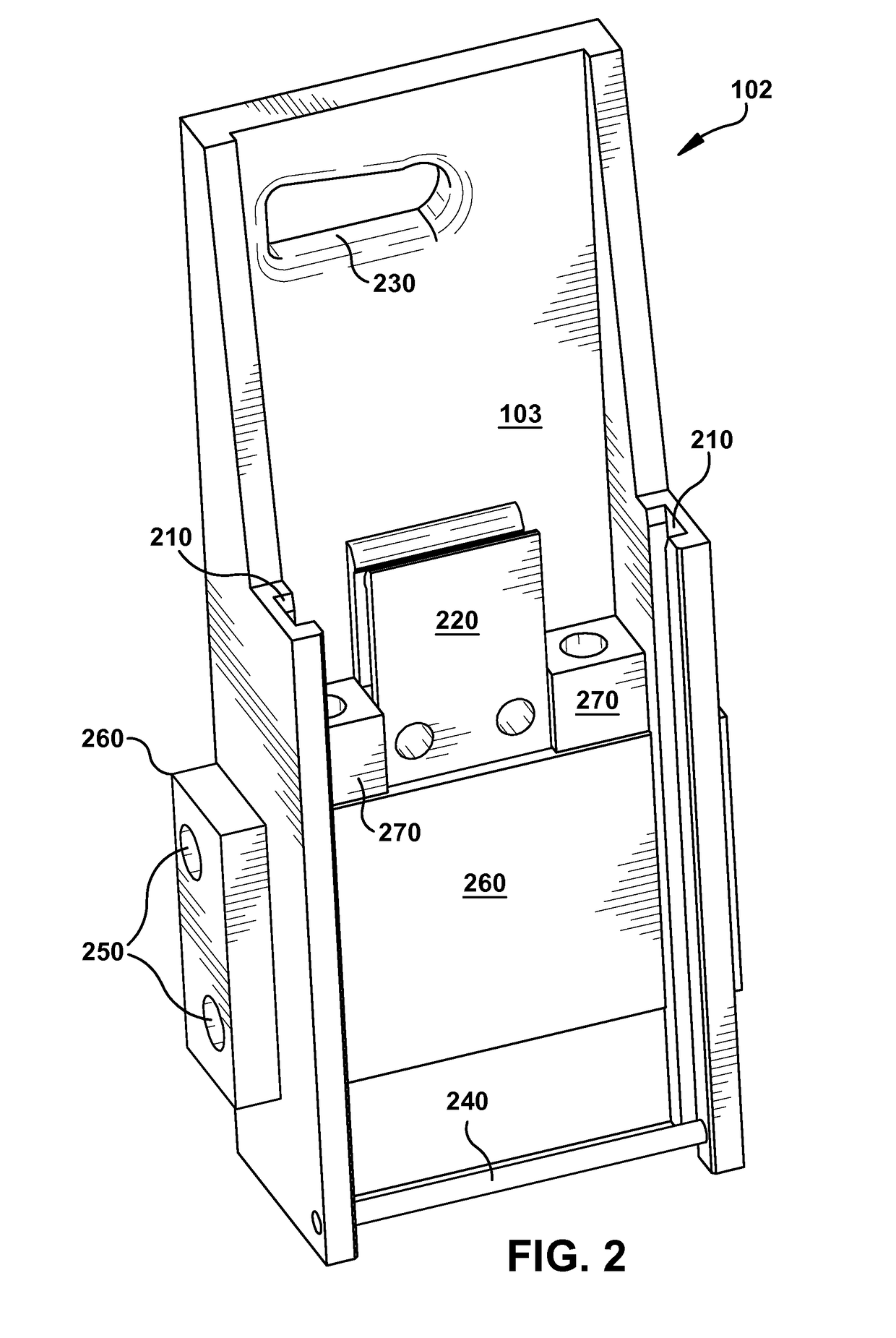
[0020]Aspects of the invention provide for a brush holder assembly (or apparatus) configured to conduct electrical current between a brush and a rotating element of a dynamoelectric machine (e.g., an electrical generator, electrical motor, etc.) and / or another rotating machine (e.g., a rotating crane). In particular, aspects of the invention provide for a brush holder assembly that may aid an operator in safely removing / replacing brushes in a dynamoelectric machine and / or another rotating machine.

[0021]As described herein, conventional dynamoelectric machines include a rotor having windings that conduct electrical current during operation of the machine. As the rotor rotates, rotating elements are used to conduct current to the rotor windings from a source external to the rotor. The rotating elements such as collector rings or commutators make contact with brushes to conduct the current. As the brushes are stationary with respect to the rotating elements, the brushes, which are made...


PUM


Abstract

A brush holder apparatus includes a stationary support member having at least one groove, and a fork electrical connector. The stationary support member has a conductive bar configured to pass through a portion of the stationary support member's main body. The conductive bar is configured to provide electrical conductivity with a collector mount and the fork electrical connector. A brush retainment member is configured to be releasably affixed to the stationary support member. The brush retainment member has at least one rail configured to slide along the at least one groove, and a knife electrical connector configured to mate with the fork electrical connector. The stationary support member is configured for electrical connection to a collector mount and the brush retainment member is configured to retain at least one brush.

Description

BACKGROUND OF THE INVENTION[0001]The subject matter disclosed herein relates to a brush holder apparatus and system. Specifically, the subject matter disclosed herein relates to a brush holder apparatus and system configured to conduct electrical current between a brush and a rotating element of a dynamoelectric machine (e.g., an electrical generator, electrical motor, etc.) and / or another rotating machine (e.g., a rotating crane).[0002]Conventional dynamoelectric machines include a rotor having windings that conduct electrical current during operation of the machine. As the rotor rotates, rotating elements are used to conduct current to the rotor windings from a source external to the rotor. The rotating elements such as collector rings or commutators make contact with brushes to conduct the current. As the brushes are stationary with respect to the rotating elements, the brushes, which are made of carbon, wear due to friction and need periodic replacement.[0003]Due to a desire to ...

Claims


Application Information

Patent Timeline
Patent Type & Authority Patents(United States)
IPC IPC(8): H01R39/38H01R43/14H02K13/00H01R39/58H02K5/14
CPCH01R39/385H01R39/58H01R43/14H02K5/148H02K13/00H02K2205/06
Inventor STEINBACH, ALBERT EUGENESCALZO, III, FRANK AUSTIN
Owner GENERAL ELECTRIC CO
Why Eureka
Try Eureka