Light emitting device

a technology of light-emitting devices and sealing resins, which is applied in the direction of semiconductor devices, luminescent compositions, chemistry apparatus and processes, etc., can solve the problems of sealing resin unexpected leakage and spread from the recessed portion of the package onto the upper surfa

Active Publication Date: 2017-05-16
NICHIA CORP
View PDF47 Cites 0 Cited by
  • Summary
  • Abstract
  • Description
  • Claims
  • Application Information

AI Technical Summary

Benefits of technology

[0007]The present invention has been made in view of the foregoing circumstances, and it is an object of embodiments of the present invention to provide a light emitting device that can suppress the leakage and spread of a sealing member from a recessed portion of a base substrate onto an upper surface thereof.
[0009]Accordingly, embodiments of the present invention can suppress the leakage and spread of the sealing member onto the upper surface of the base substrate.

Problems solved by technology

In such a light emitting device, however, the sealing resin unexpectedly leaks and spreads from the recessed portion of the package onto the upper surface thereof due to high wettability of a liquid base material of the sealing resin.

Method used


Image

  • Light emitting device
  • Light emitting device
  • Light emitting device

Examples


example 1

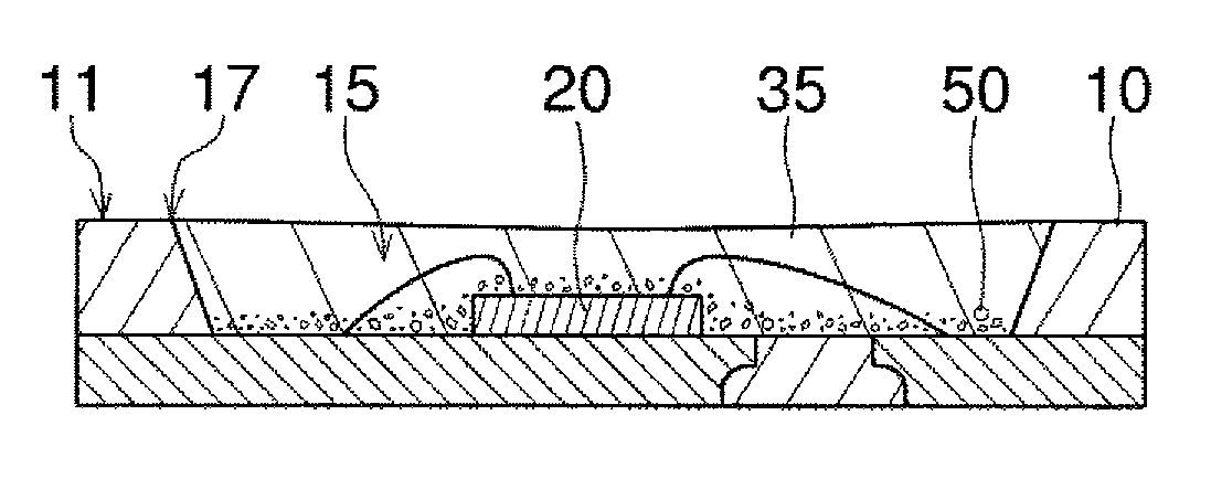
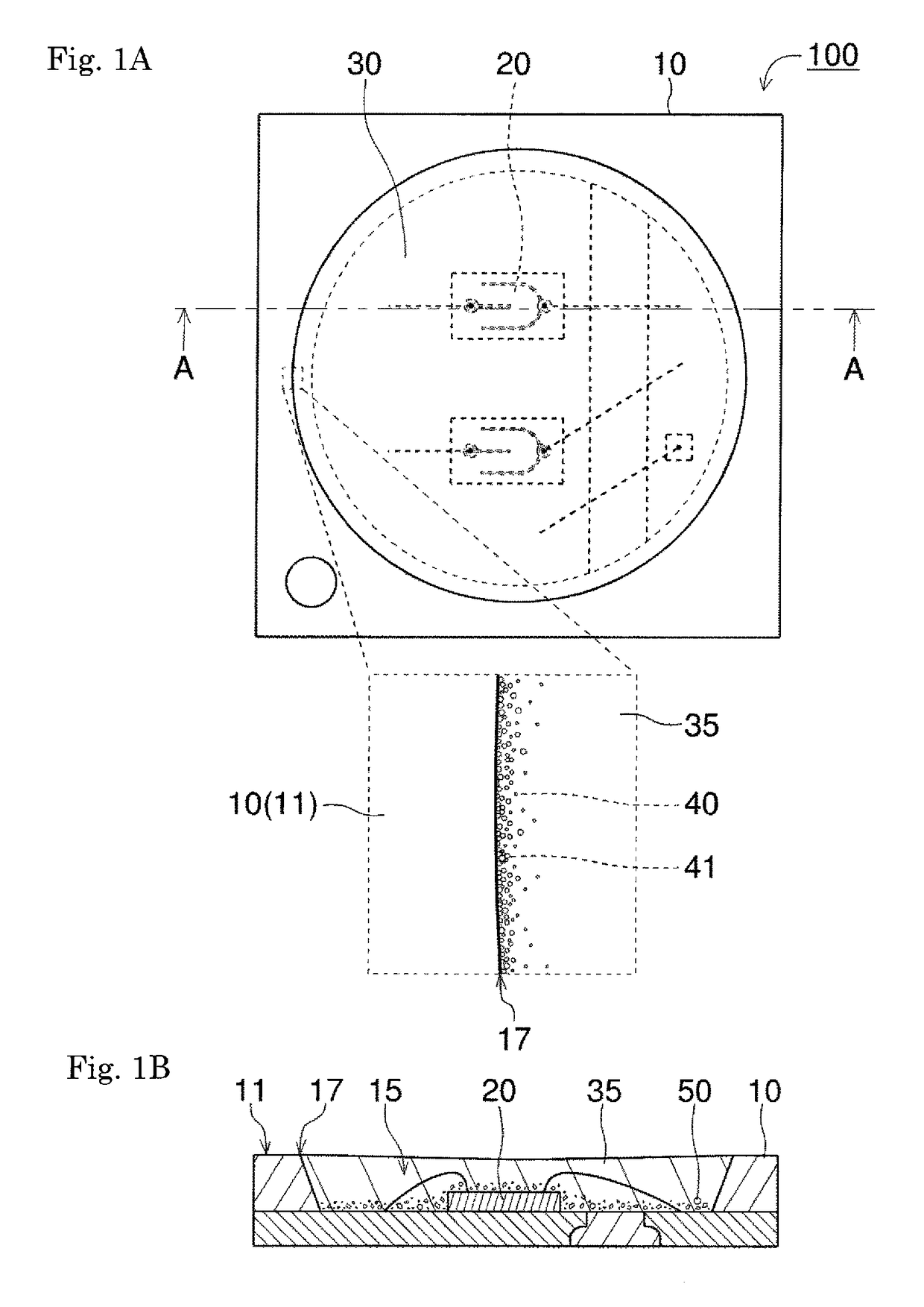
[0059]A light emitting device of Example 1 is a top-view type SMD (surface-mount-device) LED that has the structure of the light emitting device 100 shown in FIGS. 1A and 1B.

[0060]The base substrate had a rectangular parallelepiped having dimensions of 3.0 mm in length, 3.0 mm in width, and 0.52 mm in thickness. The base substrate was formed as a package made up of the molded body integrally formed with apair of (first and second) positive and negative lead electrodes. The base substrate was manufactured by setting a processed metal plate (lead frame) with a plurality of sets of lead electrodes connected in the longitudinal and lateral directions via suspension leads in a die, injecting a liquid material for the molded body into the die, solidifying the material, followed by removal of the die, and then cutting (singulating) the base substrate. In this example, the cutting of the base substrate was performed after a sealing step of the light emitting element.

[0061]Each of the first ...


PUM


Abstract

A light emitting device (100) according to the present disclosure includes a base substrate (10) having a recessed portion (15) at its upper surface (11); a light emitting element (20) provided in the recessed portion (15); and a sealing member (30) provided in the recessed portion (15), in which the sealing member (30) contains surface-treated particles (40), or particles (40) coexisting with a dispersing agent, and at least a part of an edge portion of the sealing member (30) is a region located in the vicinity of an edge (17) of the recessed portion, and in which at least one of the particles (40) and aggregates (41) of particles are unevenly distributed.

Description

CROSS-REFERENCE TO RELATED APPLICATION[0001]This application claims priority based on Japanese Patent Application No. 2013-251586 filed on Dec. 5, 2013 in Japan, which is incorporated herein by reference in its entirety.BACKGROUND OF THE INVENTION[0002]Field of the Invention[0003]The disclosure relates to a light emitting device including a light emitting element, and a sealing member for sealing the light emitting element.[0004]Description of the Related Art[0005]Conventionally, some light emitting devices are manufactured by disposing a light emitting element in a recessed portion of a package, connecting the light emitting element to a lead frame via wires, filling a sealing resin into the recessed portion, and then curing the resin (see, for example, JP 2010-080620 A and JP 2011-222718 A).[0006]In such a light emitting device, however, the sealing resin unexpectedly leaks and spreads from the recessed portion of the package onto the upper surface thereof due to high wettability ...

Claims


Application Information

Patent Timeline
Patent Type & Authority Patents(United States)
IPC IPC(8): H01L33/00H01L33/56H01L33/50H01L33/54
CPCH01L33/56H01L33/50H01L33/0095H01L33/54H01L2224/45144H01L2224/48091H01L2224/48247H01L2224/48257H01L2224/49113H01L2924/00014H01L2924/00H01L2933/0091C09K11/7774H01L33/501C09K11/025H01L33/502H01L33/508H01L33/62
Inventor KURAMOTO, MASAFUMIYAMASAKI, AKIKOICHIKAWA, HIROFUMISHIMIZU, YASUNORIOTA, AKIHIRO
Owner NICHIA CORP
Why Eureka
Try Eureka