Honing tool and method

Inactive Publication Date: 2017-05-23
EMPIRE MAGNETICS
View PDF2 Cites 8 Cited by
  • Summary
  • Abstract
  • Description
  • Claims
  • Application Information

AI Technical Summary

Benefits of technology

[0005]In the present invention, the first object is achieved by providing a rotary machining tool comprising a rotating magnetic coupling having a first cylindrical bore, a drive axle having a first primary cylindrical axis and work tool end and a driving end opposite the work tool end, wherein the drive axle is supported by one or more rotary couplings in the rotating magnetic coupling, an inner axle having a second primary cylindrical axis disposed concentrically within at least a portion of the drive axle, wherein the inner axle is supported by one or more rotary couplings in the drive axle, in which the first and second primary cylindrical axis are co-incident with a geometric center of the cy

Problems solved by technology

This reduced machine throughput potent

Method used


Image

  • Honing tool and method
  • Honing tool and method
  • Honing tool and method

Examples


Embodiment Construction

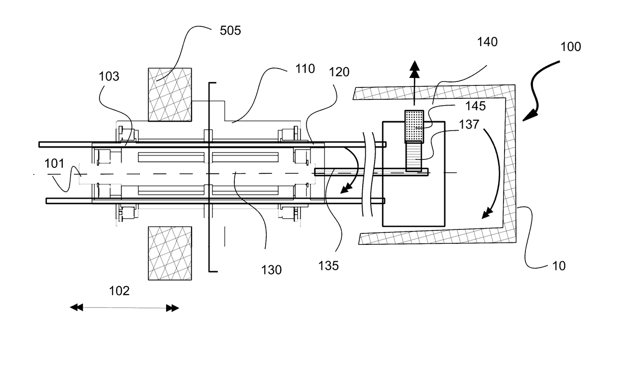
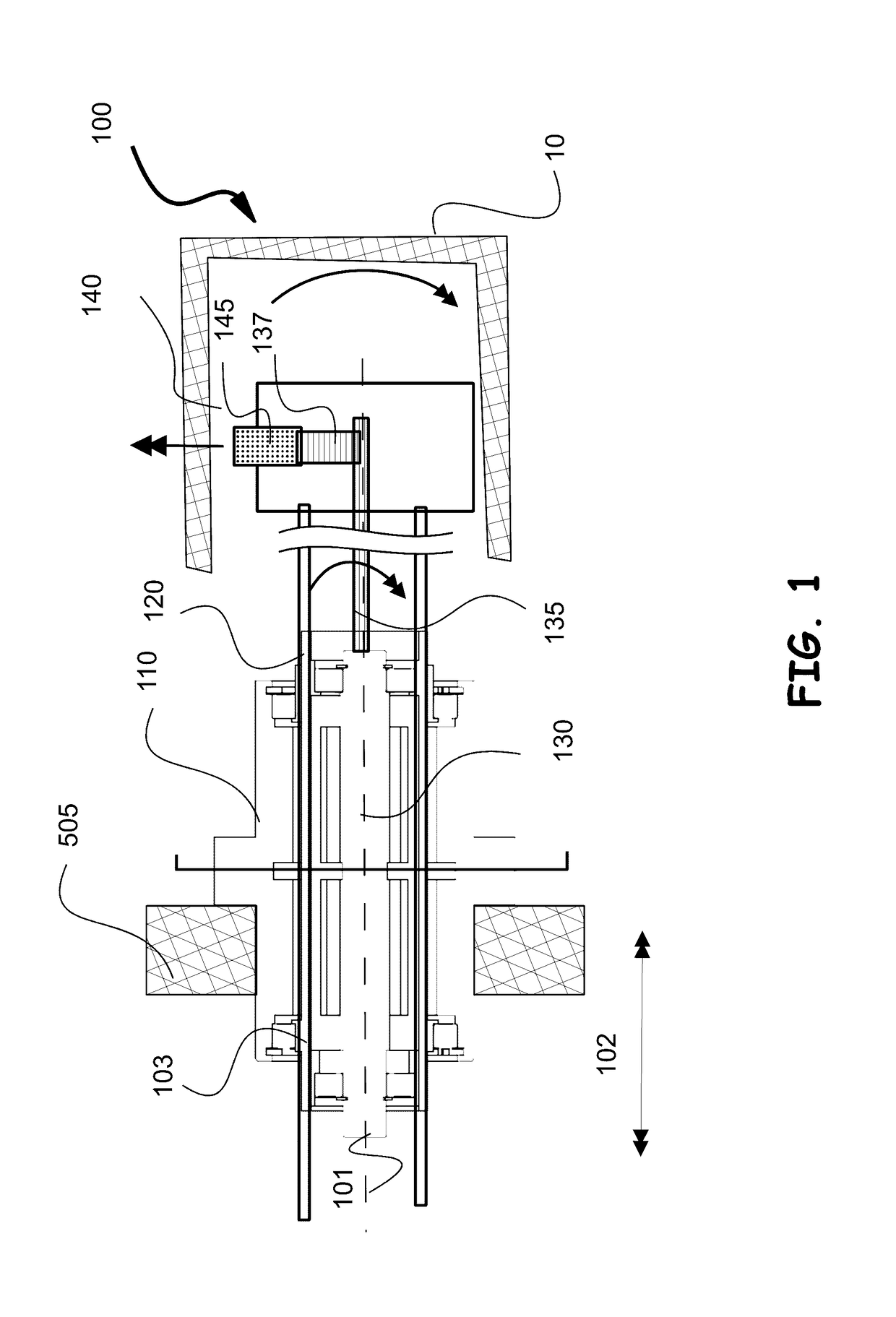
[0016]Referring to FIGS. 1 through 7, wherein like reference numerals refer to like components in the various views, there is illustrated therein a new and improved Honing Tool and Method, generally denominated 100 herein.

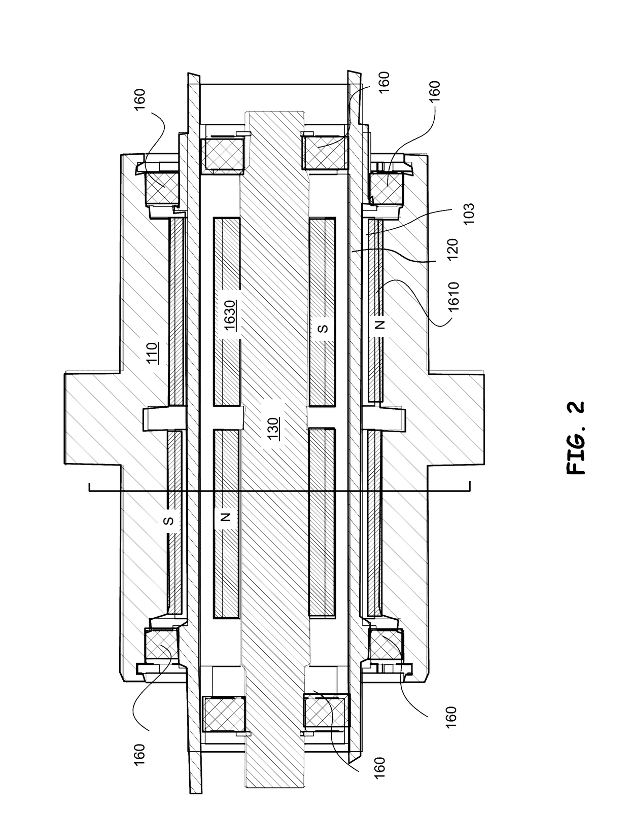
[0017]In accordance with the present invention, a honing tool 100 has a rotary magnetic coupling 110, which contains a rotating drive axle 120, as well as a concentrically disposed inner axle 130. The rotating drive axle 120 is connected to the tool head 140. Pluralities of spaced apart abrasive or sharpened cutting members 145 are disposed about the circumferential direction of the tool head 140. The abrasive / cutting members 145 are commonly referred to as honing stones, and can be adjusted in the radial displacement from the central cylindrical axis 101.

[0018]Typical mechanism for adjustment of the abrasive members 145 in a honing tool are disclosed in U.S. Pat. Nos. 2,439,117; 3,216,155 and 4,524,549, which are incorporated herein by reference. One or more honin...


PUM


Abstract

The axial rotation of a honing tool head and the radial advance of the co-rotating honing stones are accomplished simultaneously by a magnetic coupling. The magnetic coupling connects an inner and drive axle that are driven independently. When the inner axial is driven at a differential speed than the drive axle, a connected pinion gear mechanism is engaged to transfer torque and radially displace the honing stones in response to the speed difference.

Description

CROSS REFERENCE TO RELATED APPLICATIONS[0001]The present application claims the benefit of priority to the US Provisional Patent Application of the same title having application Ser. No. 61 / 859,414 which was filed on Jul. 29, 2013, and is incorporated herein by reference.BACKGROUND OF INVENTION[0002]The present invention relates to an improved honing tool and method, and more particularly to a means for moving the honing stoning radially during the honing process.[0003]Prior methods of honing require the oscillation and rotation of the honing head to advance in a stepwise fashion as the honing stones are advanced or retracted. This reduced machine throughput potential, and limits process control means.[0004]It would be an advance in the art to have a simple convenient way to move the honing stone positions continuously while material is removed in the honing process and appropriate control means during such a process to avoid excess material removal.SUMMARY OF INVENTION[0005]In the ...

Claims


Application Information

Patent Timeline
IPC IPC(8): B24B33/02B24B33/08
CPCB24B33/02B24B33/087
Inventor HALSTEAD, RICHARD
Owner EMPIRE MAGNETICS
Why Eureka
Try Eureka