Radar with low interception probability

a technology of interception probability and radar, applied in the field of radars with low interception probability, can solve the problems of limiting the use of the radar, reducing the range of the discreet radar, and exhibiting the continuous wave of the radar, so as to reduce the transmission leakage of the different transmit subarrays

Active Publication Date: 2017-05-30
THALES SA
View PDF10 Cites 3 Cited by
  • Summary
  • Abstract
  • Description
  • Claims
  • Application Information

AI Technical Summary

Benefits of technology

[0020]The radar comprises, for example, in reception, frequency filtering means adapted to reduce the transmission leaks of the different transmit subarrays.

Problems solved by technology

Also, radars with continuous waves exhibit a major drawback, relating to the coupling between the transmission and the reception which are simultaneous, which tends to greatly limit their use when the required range is great, typically beyond one to several tens of km.
A first problem to be resolved is therefore how to strengthen the “discretionary” nature of the radars in order for their detection to be as difficult as possible.
A second problem is how to increase the range of the discreet radars.
Through their design, the abovementioned LPI radars are difficult to detect.
The LPI radars are difficult to detect by conventional detectors which seek to detect a peak high power radar pulse.
Moreover, the radars with continuous or quasi-continuous transmission are limited in range, because of the leaks between the transmitter and the receiver.

Method used


Image

  • Radar with low interception probability
  • Radar with low interception probability
  • Radar with low interception probability

Examples


Embodiment Construction

[0045]Before describing an example of a radar according to the invention and its implementation, a few recaps concerning the principles used in transmission and in reception of the signal will be explained for a radar comprising, in the transmitter, an array antenna in transmission and an array antenna in reception in accordance with the abovementioned MIMO architectures. Each of these antennas consists, for example, of subarrays that are identical and non-directional in at least one plane in transmission.

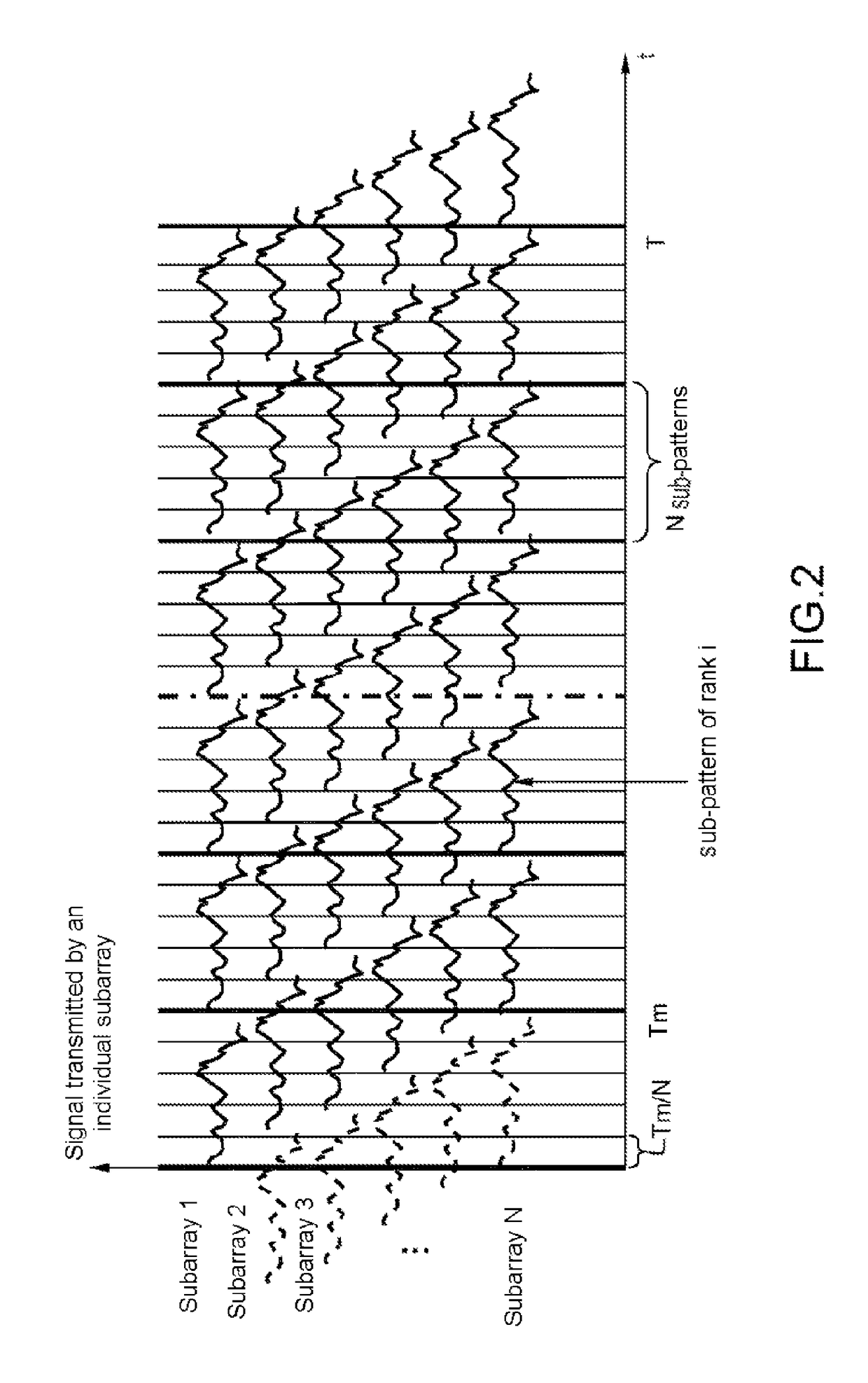
[0046]FIG. 1 schematically represents, in a system of axes in which the x axis represents the time and the y axis the amplitude of the signal transmitted by an individual subarray, a wave train transmitted by the subarray of rank i.

[0047]In transmission, all the individual subarrays of the transmit antenna simultaneously transmit one and the same wave train on a carrier frequency f, with, for each individual subarray, a different delay τ relative to a common time origin. This wave ...


PUM


Abstract

A radar and method for making a radar undetectable, comprising comprises: on a transmit antenna consisting of N individual subarrays that are non-directional in at least one plane in transmission, each being linked to a waveform generator, generating, for each of the individual subarrays, a waveform so as to make each of the individual subarrays transmit continuous or quasi-continuous signals according to a temporal and periodic pattern by using transmission patterns made up of N different subarrays and which are deduced from one another by an individual delay, on the receive antenna comprising M individual subarrays adapted to pick up the reflected signals obtained from the transmission of the N individual subarrays of the transmit antenna, performing a compression of the received signal in space and in time of the received signals.

Description

CROSS-REFERENCE TO RELATED APPLICATIONS[0001]This application is a National Stage of International patent application PCT / EP2013 / 054041, filed on Feb. 28, 2013, which claims priority to foreign French patent application No. FR 1200627, filed on Mar. 2, 2012, the disclosures of which are incorporated by reference in their entirety.FIELD OF THE INVENTION[0002]The invention relates to radars with low interception probability which are difficult to detect.[0003]It applies to radars that have an SAR function.BACKGROUND[0004]These days there exist radars with low probability of intercept, abbreviated LPI, which mostly use continuous or quasi-continuous transmission techniques, aiming to reduce the transmitted peak power.[0005]These continuous transmission techniques, when they are employed alone, can be controlled by the implementation of modern detectors that use suitable processing operations that allow for a coherent integration of the signal over a long time, typically from one to sev...

Claims


Application Information

Patent Timeline
Patent Type & Authority Patents(United States)
IPC IPC(8): G01S7/282G01S7/35G01S13/34G01S13/90G01S13/02
CPCG01S7/35G01S13/02G01S13/343G01S13/9035G01S2013/0281G01S13/904
Inventor CORNIC, PASCALKEMKEMIAN, STEPHANEARTIS, JEAN-PAUL
Owner THALES SA
Why Eureka
Try Eureka