Isolation tuners for directional couplers

a technology of isolation tuners and directional couplers, which is applied in the field of radio frequency (rf) communication devices, can solve the problems of a mono-static rfid reader receiver with limited transmission leakage, a higher level of transmission leakage likely to be observed on a mono-static reader, and overlapped transmission and received signals of a transceiver in terms of frequency spectrum

Active Publication Date: 2014-09-04
APPLIED WIRELESS IDENTIFICATIONS GROUP
View PDF3 Cites 18 Cited by
  • Summary
  • Abstract
  • Description
  • Claims
  • Application Information

AI Technical Summary

Benefits of technology

[0008]To overcome the forgoing disadvantages, various embodiments described and / or suggested herein preferably include circuitry to reduce the transmission leakage at the receiver, e.g., in back-scatter detection radio systems.

Problems solved by technology

However, the transmitted and received signals for a transceiver may overlap in terms of frequency spectrum, as the received signals may have a frequency separation too small to be easily filtered.
Unlike bi-static readers, whose leakage factors are mostly determined by the isolation of their antennas, the transmission leakage at the receivers of a mono-static RFID reader is mostly limited by the imperfect reflection coefficient of the shared antenna, transmission line, coupler, terminator, and / or circulator.
Therefore, a higher level of transmission leakage is likely to be observed on a mono-static reader.
Moreover, any movement of objects near the antenna at the installation site also affect the impedance of antenna, thereby further altering the transmission to reception leakage ratio.
The environmental effect of the mono-static RFID reader is a significant source of degradation of the transmission to reception leakage.

Method used


Image

  • Isolation tuners for directional couplers
  • Isolation tuners for directional couplers
  • Isolation tuners for directional couplers

Examples


Embodiment Construction

[0020]The following description is made for the purpose of illustrating the general principles of the present invention and is not meant to limit the inventive concepts claimed herein. Further, particular features described herein can be used in combination with other described features in each of the various possible combinations and permutations.

[0021]Unless otherwise specifically defined herein, all terms are to be given their broadest possible interpretation including meanings implied from the specification as well as meanings understood by those skilled in the art and / or as defined in dictionaries, treatises, etc.

[0022]It must also be noted that, as used in the specification and the appended claims, the singular forms “a,”“an” and “the” include plural referents unless otherwise specified.

[0023]Illustrative examples of RFID systems, including RFID tags and readers, are described in U.S. patent application Ser. No. 11 / 367,061 filed Mar. 3, 2006 which is incorporated by reference....


PUM


Abstract

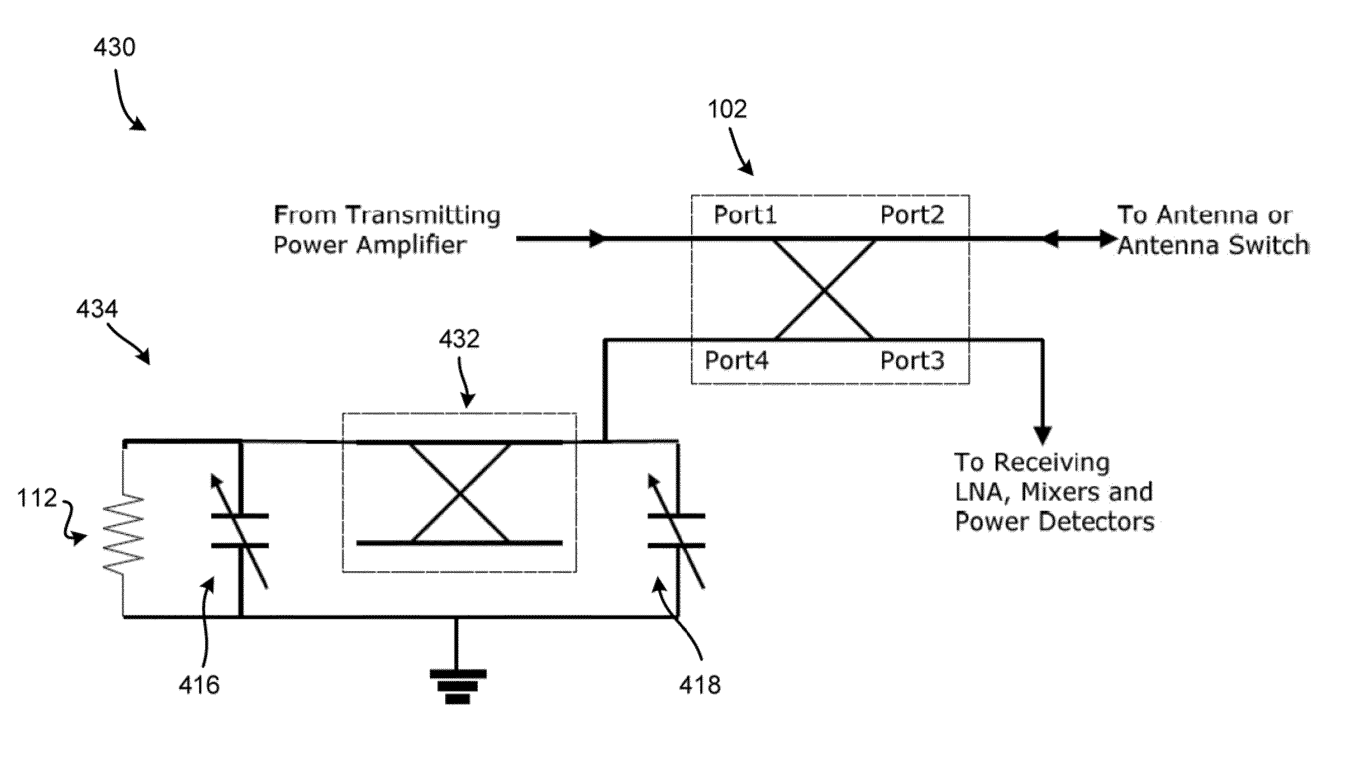
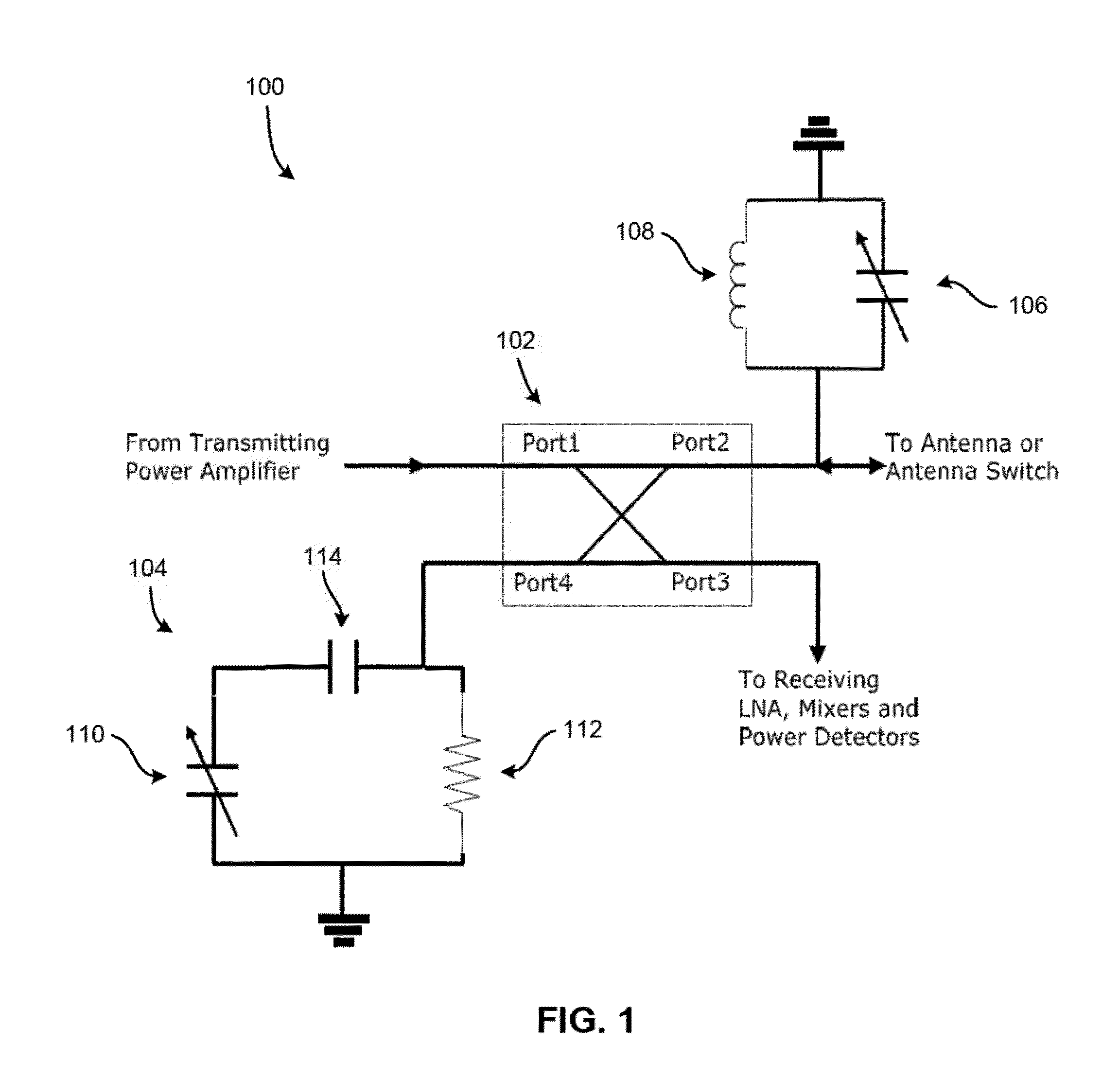
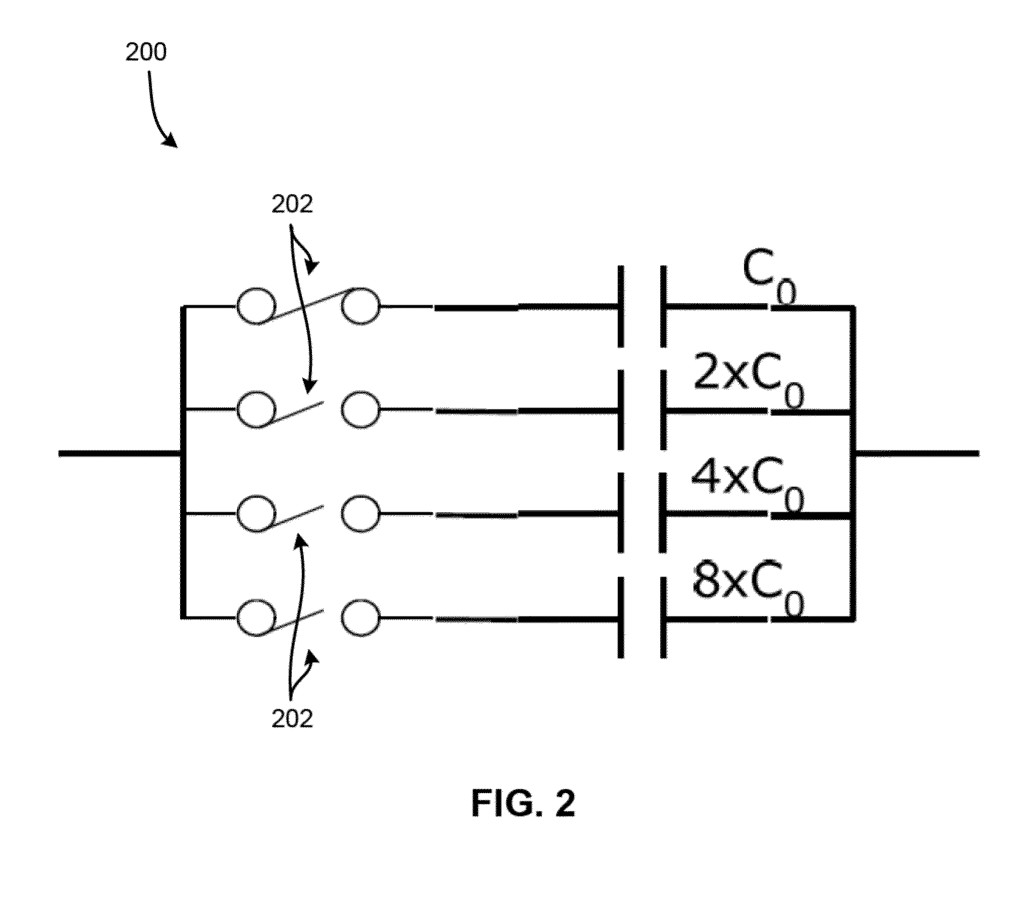
A device according to one embodiment includes a variable-capacitor-tuned isolation tuning circuit having a directional coupler having an input port, an output port, an isolation port, and a coupling port. The variable-capacitor-tuned isolation tuning circuit also has and a tunable capacitor coupled in shunt to the coupling port of the directional coupler.

Description

RELATED APPLICATIONS[0001]This application claims priority from U.S. Provisional Patent Application No. 61 / 772,482 filed on Mar. 4, 2013, which is herein incorporated by reference.FIELD OF THE INVENTION[0002]The present invention relates to Radio Frequency (RF) communication devices, and more particularly, this invention relates to circuitry to reduce the transmission leakage to the reception channel of radio systems.BACKGROUND[0003]Back-scattering detection systems, including frequency modulated continuous wave (FMCW) radars and radio frequency identifications (RFID) readers, simultaneously transmit an RF carrier wave and receive backscattered radio waves through their antennas. However, the transmitted and received signals for a transceiver may overlap in terms of frequency spectrum, as the received signals may have a frequency separation too small to be easily filtered. Therefore, the leading transmitted signal becomes a potential blocking signal to the back-scattered signal at t...

Claims


Application Information

Patent Timeline
Patent Type & Authority Applications(United States)
IPC IPC(8): H01P5/04H04B1/44H01P5/18
CPCH01P5/04H04B1/44H01P5/18H04B1/0458H04B1/10H04B1/525
Inventor ZHOU, LIMING
Owner APPLIED WIRELESS IDENTIFICATIONS GROUP
Why Eureka
Try Eureka