
Refrigerating device

a refrigerating device and refrigeration technology, applied in the direction of refrigeration safety arrangement, refrigeration components, light and heating apparatus, etc., can solve the problems of increasing manufacturing costs, and achieve the effect of high reliability of refrigerating devices

Active Publication Date: 2017-06-13
DAIKIN IND LTD
View PDF9 Cites 0 Cited by
  • Summary
  • Abstract
  • Description
  • Claims
  • Application Information

AI Technical Summary

Benefits of technology

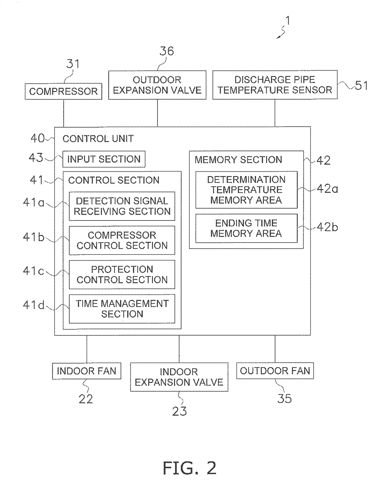
[0017]In the refrigerating device according to the first aspect of the present invention, transitions following the starting of the compressor and steady states in which the state of the refrigerant is stable are judged, and protection control of the compressor is performed based on the determination temperatures which is different between during transitions and during steady states. Therefore, even when the temperature difference between the detected temperature and the internal temperature of the compressor during a transition is different from the temperature difference between the detected temperature and the internal temperature of the compressor during a steady state, appropriate protection control can be performed before the interior of the compressor overheats. As a result, a highly reliable refrigerating device is achieved.
[0018]In the refrigerating device according to the second aspect of the present invention, a transition can be determined in a simple and appropriate manner and the appropriate protection control can be performed before the interior of the compressor overheats. As a result, a highly reliable refrigerating device is achieved.
[0019]In the refrigerating device according to the third aspect of the present invention, the end of the transition can easily be judged to vary the determination temperature. Therefore, the appropriate protection control can be performed before the interior of the compressor overheats. As a result, a highly reliable refrigerating device is achieved.
[0020]In the refrigerating device according to the fourth aspect of the present invention, the appropriate protection control can be performed when the temperature difference between the detected temperature and the internal temperature of the compressor is greater during a transition following a starting of the compressor than during a steady state.

Problems solved by technology

However, it is difficult to install a temperature detector in the compressor interior because this leads to an increase in manufacturing cost; therefore, a determination temperature is decided with the presupposition that there will be a fixed temperature difference between the internal temperature of the compressor and the temperature of the discharge pipe, and protection control is performed using the temperature of the discharge pipe of the compressor.

Method used


Image

  • Refrigerating device
  • Refrigerating device
  • Refrigerating device

Examples


Embodiment Construction

[0026]An embodiment of the present invention is described below with reference to the drawings. The following embodiment of the present invention can be modified as appropriate within a range that does not deviate from the scope of the present invention.

[0027](1) Overall Configuration

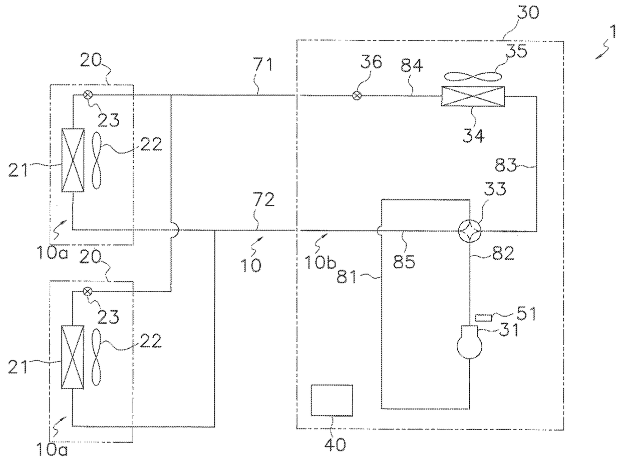
[0028]An air conditioning device 1, given as an embodiment of a refrigerating device according to the present invention, is capable of operating while switching between a cooling operation and a heating operation.

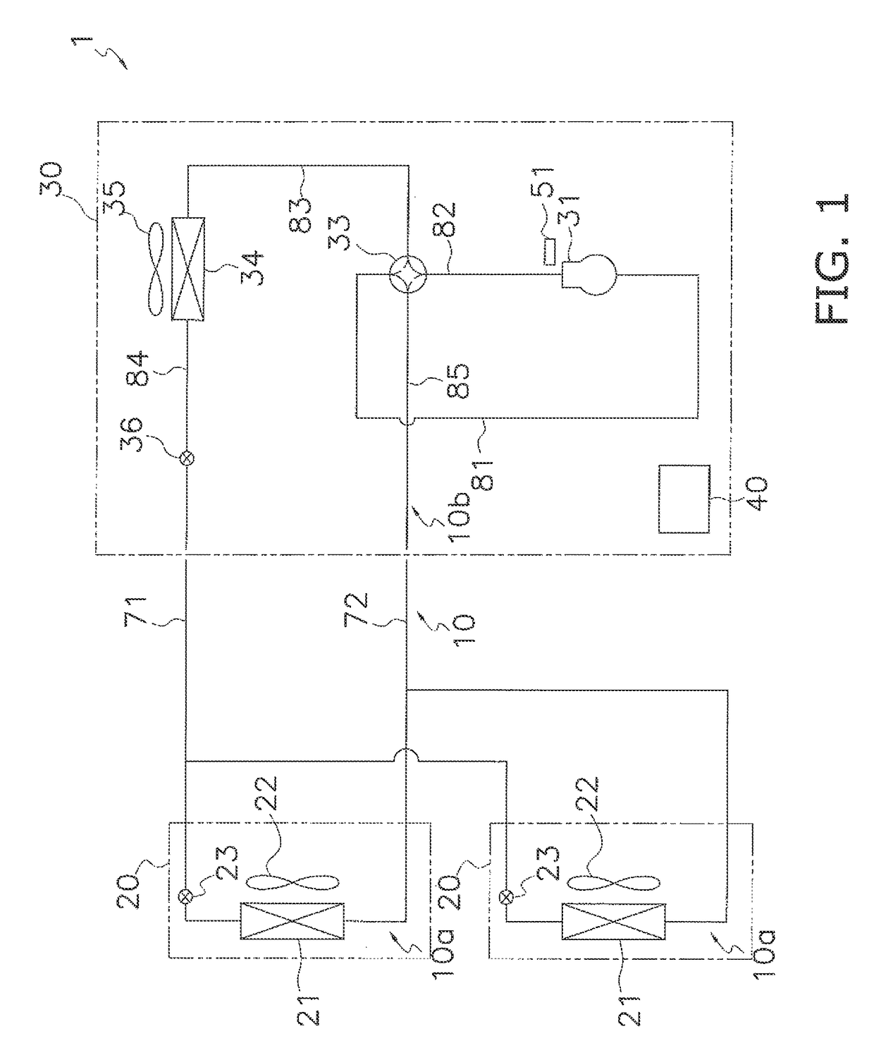
[0029]The air conditioning device 1 has primarily indoor units 20, an outdoor unit 30, and a control unit 40, as shown in FIG. 1. There are two indoor units 20 in FIG. 1, but there may be three or more or only one.

[0030]The air conditioning device 1 has a refrigerant circuit 10 filled with R32 as a refrigerant. The refrigerant circuit 10 has indoor side circuits 10a accommodated in the indoor units 20, and an outdoor side circuit 10b accommodated in the outdoor unit 30. The indoor side circuits...


PUM


Abstract

A refrigerating device includes a compressor, a temperature detector and a protection control section. The compressor compresses a refrigerant. The temperature detector detects a temperature of the refrigerant discharged from the compressor on an outside of the compressor. The protection control section judges that a transition following a starting of the compressor is in effect and that a steady state following an end of the transition in which a state of the refrigerant is stable is in effect, performs protection control on the compressor when a detected temperature detected by the temperature detector exceeds a first determination temperature during the transition, and performs the protection control on the compressor when the detected temperature exceeds a second determination temperature during the steady state.

Description

CROSS-REFERENCE TO RELATED APPLICATIONS[0001]This U.S. National stage application claims priority under 35 U.S.C. §119(a) to Japanese Patent Application No. 2012-133932, filed in Japan on Jun. 13, 2012, the entire contents of which are hereby incorporated herein by reference.TECHNICAL HELD[0002]The present invention relates to a refrigerating device.BACKGROUND ART[0003]Refrigerating devices are known to have configurations such that, in order to prevent breakages and lower performance of a compressor which configures a refrigerant circuit due to overheating, a temperature of a discharge pipe of the compressor is monitored and a protection control is performed on the compressor when this temperature is larger than a determination temperature.[0004]To protect the compressor, it is more preferable to monitor the internal temperature of the compressor, which is higher than the temperature of the discharge pipe, in more detail, to monitor the temperature of refrigerant immediately after ...

Claims


Application Information

Patent Timeline
Patent Type & Authority Patents(United States)
IPC IPC(8): F25B41/04F25B13/00F25B49/02F25B49/00F25B1/00
CPCF25B49/022F25B13/00F25B49/005F25B2313/005F25B2313/006F25B2313/0233F25B2313/02741F25B2500/08F25B2500/26F25B2600/025F25B2600/23F25B2700/21152
Inventor NAKAI, AKINORITOYODA, DAISUKE
Owner DAIKIN IND LTD
Learn More