
Refrigerating device

a refrigerating device and temperature technology, applied in the direction of refrigerating machines, temperature measurement of flowing materials, refrigeration safety arrangements, etc., to achieve the effect of high reliability, high reliability and high reliability of refrigerating devices

Active Publication Date: 2015-05-21
DAIKIN IND LTD
View PDF11 Cites 3 Cited by
  • Summary
  • Abstract
  • Description
  • Claims
  • Application Information

AI Technical Summary

Benefits of technology

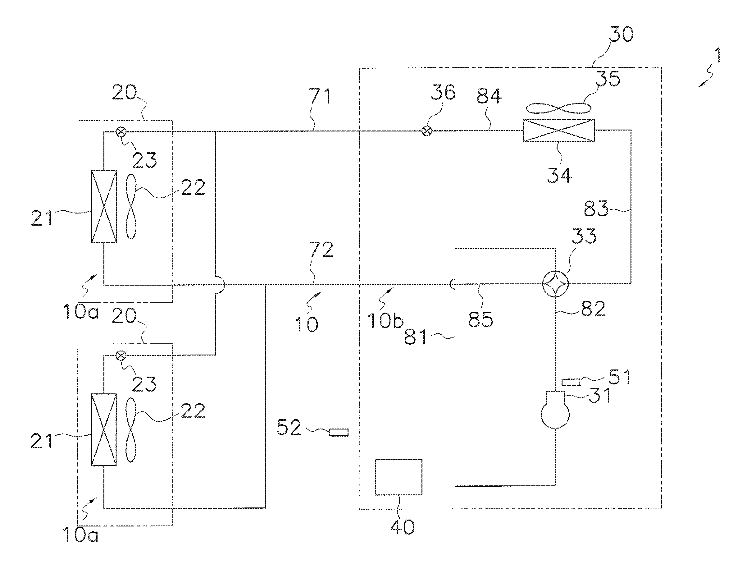
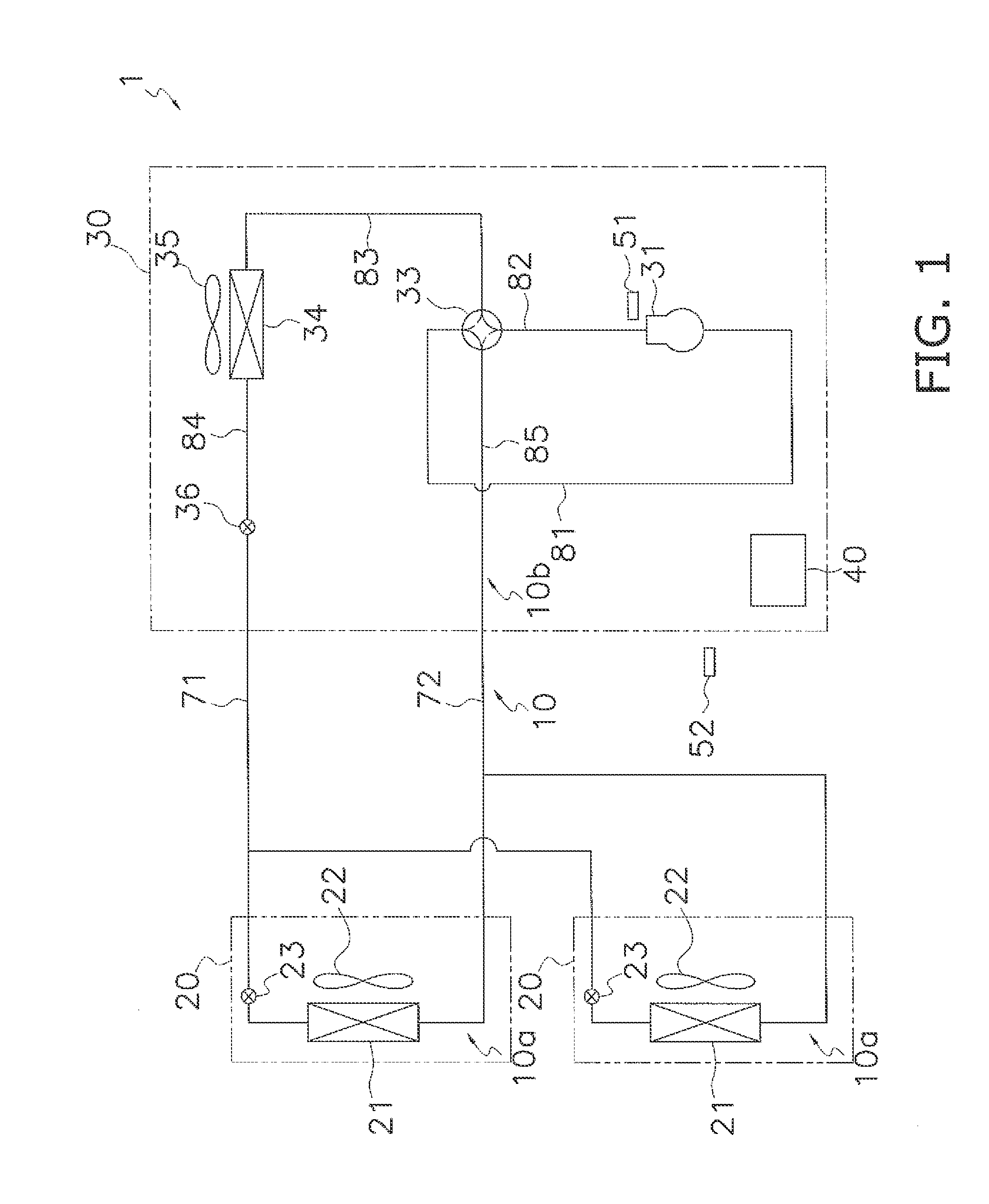
The present invention relates to a refrigerating device with a function of performing protection control. The invention is made by modifying the determination temperature, which is the reference for starting performance of protection control, based on the outside air temperature and / or type of refrigerant. This allows for appropriate protection control even when the difference in temperatures between the inside of the compressor and the temperature of refrigerant outside the compressor changes due to the outside air temperature or type of refrigerant. This improves the reliability of the refrigerating device. Additionally, the invention allows for a more precise protection control based on the detection temperature and the circumstances of the refrigerating device. Overall, this invention provides a highly reliable and efficient refrigerating device.

Problems solved by technology

However, since there are difficulties in that arranging a temperature detector inside the compressor because of the hike of the manufacturing cost, a determination temperature is set on the premise that there is a fixed difference in temperatures between the temperature of the inside of the compressor and the temperature of the discharge pipe and the protection control is performed using the temperature of the discharge pipe of the compressor.

Method used


Image

  • Refrigerating device
  • Refrigerating device
  • Refrigerating device

Examples


example b

(5-2) Modified Example B

[0137]In the embodiment described above, the first to third determination temperatures T1 to T3 are modified according to the type of refrigerant which is being used and the outside air temperature To, but the present invention is not limited to this and the first to third determination temperatures T1 to T3 may be modified according to the type of refrigerant which is being used or the outside air temperature To.

[0138]However, it is desirable that the first to third determination temperatures T1 to T3 are modified according to both the type of refrigerant which is being used and the outside air temperature To in order to perform more appropriate protection control.

example c

(5-3) Modified Example C

[0139]In the embodiment described above, the first to third protection control are executed as the protection control, but the present invention is not limited to this and more types of protection control may be performed.

[0140]In addition, there may be two or fewer types of protection control but it is desirable that all of the first to third protection control are performed in order to realize more precise protection control.

example d

(5-4) Modified Example D

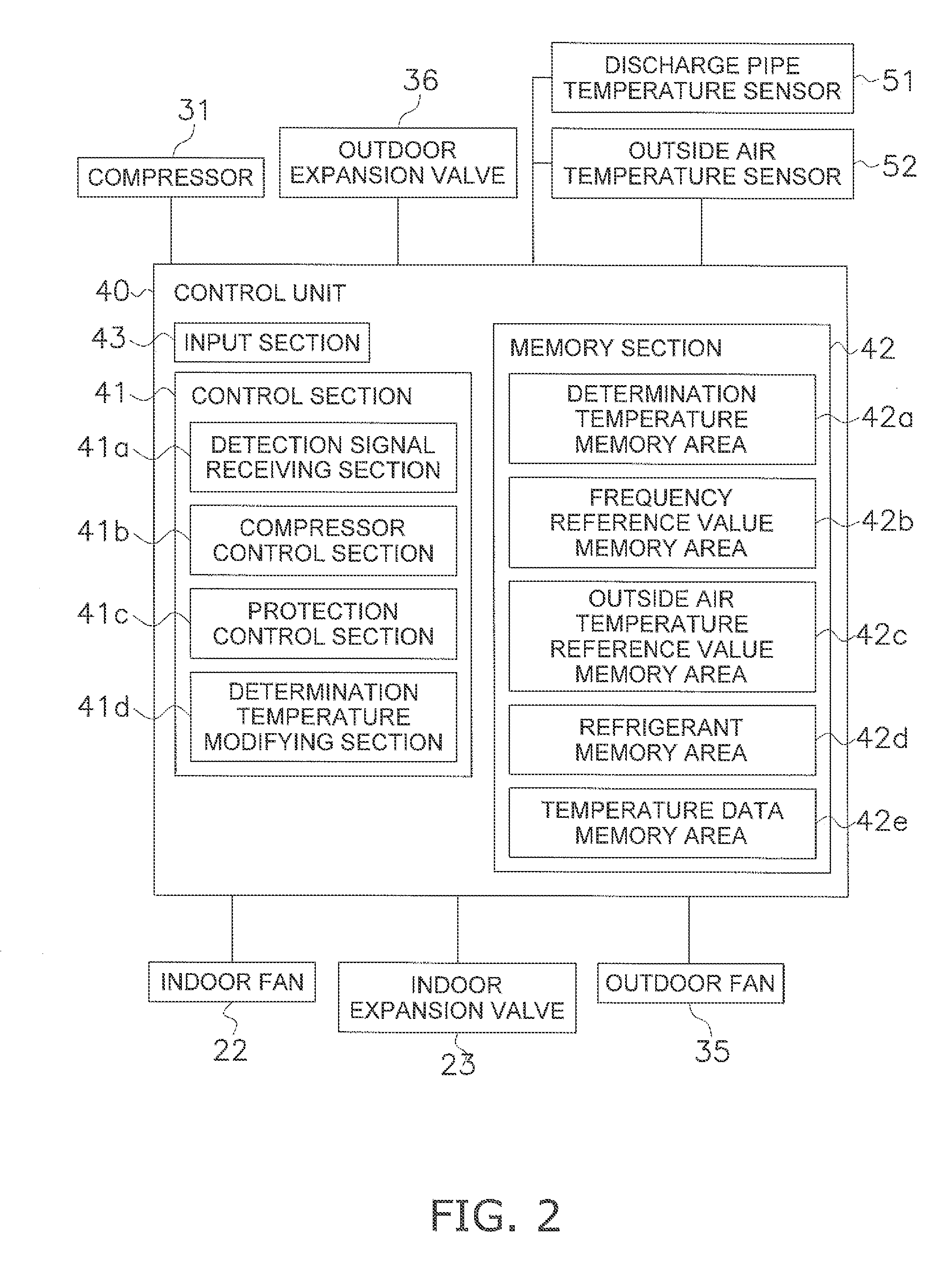
[0141]In the embodiment described above, the determination temperature modifying section 41d modifies the combination of the first to third determination temperatures T1 to T3 in the determination temperature memory area 42a to the combination of the first to third determination temperatures T1 to T3 which is stored in the temperature data memory area 42e, but the present invention is not limited to this. For example, the determination temperature modifying section 41d may calculate the first to third determination temperatures T1 to T3 which are used by the protection control section 4ic using a function where the outside air temperature To and the driving frequency f are variables (a function where the respective first to third determination temperatures T1 to T3 become smaller values as the outside air temperature To falls and as the driving frequency f is reduced). In addition, a plurality of functions may be prepared according to the types of refrigerant...


PUM

PropertyMeasurementUnit
temperatureaaaaaaaaaa
frequencyaaaaaaaaaa
driving frequencyaaaaaaaaaa

Abstract

A refrigerating device includes a refrigerant circuit, a temperature detecting unit, a protection control section, and a determination temperature modifying section. The refrigerant circuit includes a compressor to compress a refrigerant. The temperature detecting section detects a temperature of the refrigerant discharged from the compressor on an outside of the compressor. The protection control section performs protection control of the compressor in a case where a detection temperature detected by the temperature detecting section exceeds a determination temperature. The determination temperature modifying section modifies the determination temperature according to at least one of information on an outside air temperature and information on a type of the refrigerant.

Description

TECHNICAL FIELD[0001]The present invention relates to a refrigerating device.BACKGROUND ART[0002]A configuration for a refrigerating device is known where, in order to prevent breakages and lower performance of a compressor which configures a refrigerant circuit due to overheating, a temperature of a discharge pipe of the compressor is monitored and a protection control is performed on the compressor in a case where this temperature is larger than a determination temperature.[0003]Here, to protect the compressor, it is more desirable to monitor the temperature inside the compressor which has a higher temperature than the temperature of the discharge pipe, in more detail, to monitor the temperature of refrigerant immediately after being discharged from a compression chamber (the temperature of a discharge port) or the temperature of a motor, than to monitor the temperature of the discharge pipe of the compressor. However, since there are difficulties in that arranging a temperature d...

Claims


Application Information

Patent Timeline
Patent Type & Authority Applications(United States)
IPC IPC(8): F25B49/02F25B49/00G01K13/02
CPCF25B49/022F25B49/005G01K13/02F25B13/00F25B2313/006F25B2313/0233F25B2313/02741F25B2600/025F25B2600/23F25B2600/2513F25B2700/2106F25B2700/21152
Inventor NAKAI, AKINORITOYODA, DAISUKE
Owner DAIKIN IND LTD
Learn More